ADJUSTING THE BLADE TENSION
 Disconnect the machine from the power source!
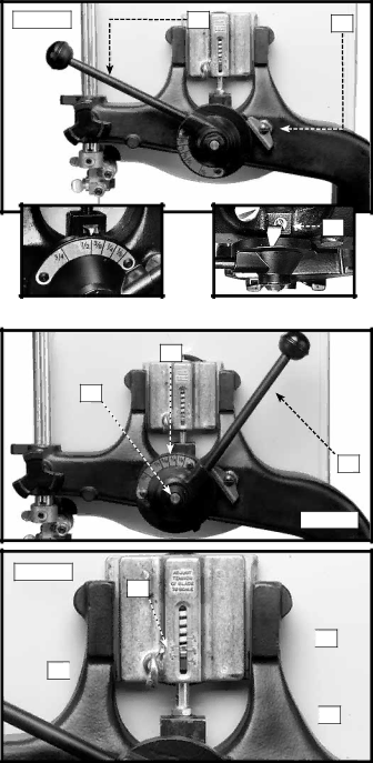
To apply tension to the blade, move the tension handle (A) Fig. 46 to the left. To release the blade tension, move the tension handle slightly to the left, lift the lever lock (B) Fig. 46 and move the tension handle (A) to the right (Fig. 47).
To adjust the blade tension:
1.Move the tension handle (A) slightly to the left, lift the lever lock (B) Fig. 46, and move the blade tension handle to the right.
2.You can set the blade tension lever to match blade widths 3/4", 1/2", 3/8", 1/4", and 1/8" (See Inset 1 - Fig.46).
Fig. 46 | A | B |
|
| A |
Inset 1 |
| Inset 2 |
3.Move the blade tension lever to the right as far as it will go. Pull outward (away from the saw) on the entire handle assembly (A) Fig. 47, and turn the the assembly until the appropriate width of the blade is shown on the top of the blade tension scale (C). Release the handle assembly so that the handle is contacting the hub (D).
NOTE: To adjust the pointer on the blade tension scale, loosen the screw (A) Inset 2 - Fig. 46, move the pointer, and tighten the screw.
4.Move the blade tension lever to the left until the lever lock (B) Fig. 46 engages the blade tension lever handle (A).
5.To
6.A series of graduations (T) Fig. 48 is located on the back of the upper
NOTE: These graduations are correct for average work, and will not be affected by rebrazing of the saw blade.
C
D
A
Fig. 47
Fig. 48
B
![]()
![]() T
T
C ![]()
![]()
![]()
![]() N
N
![]() When cutting thin pieces (3/4" or less), set the blade tension below the maximum setting for blade width to extend the life of the blade.
When cutting thin pieces (3/4" or less), set the blade tension below the maximum setting for blade width to extend the life of the blade.
![]()
20