1 Overview
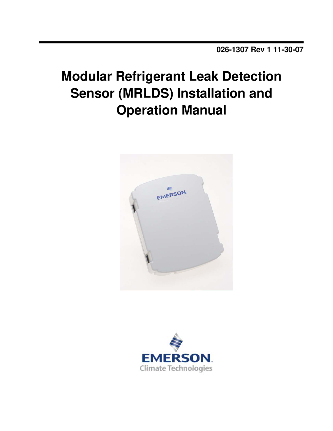
CPC specs a modular refrigerant leak detection sensor (MRLDS) that continuously monitors for low levels of refrigerants most commonly used in commercial refrigera- tion systems.
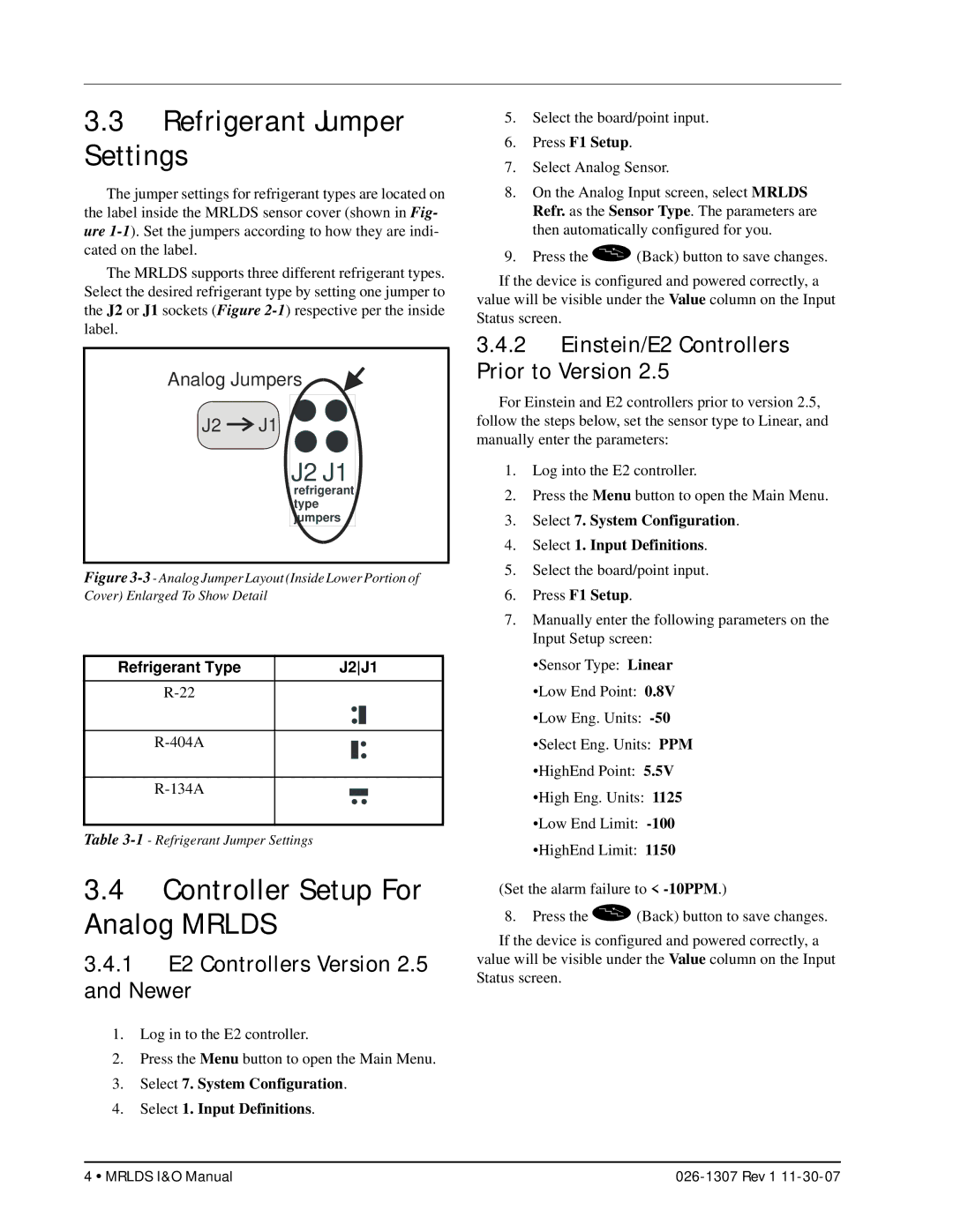
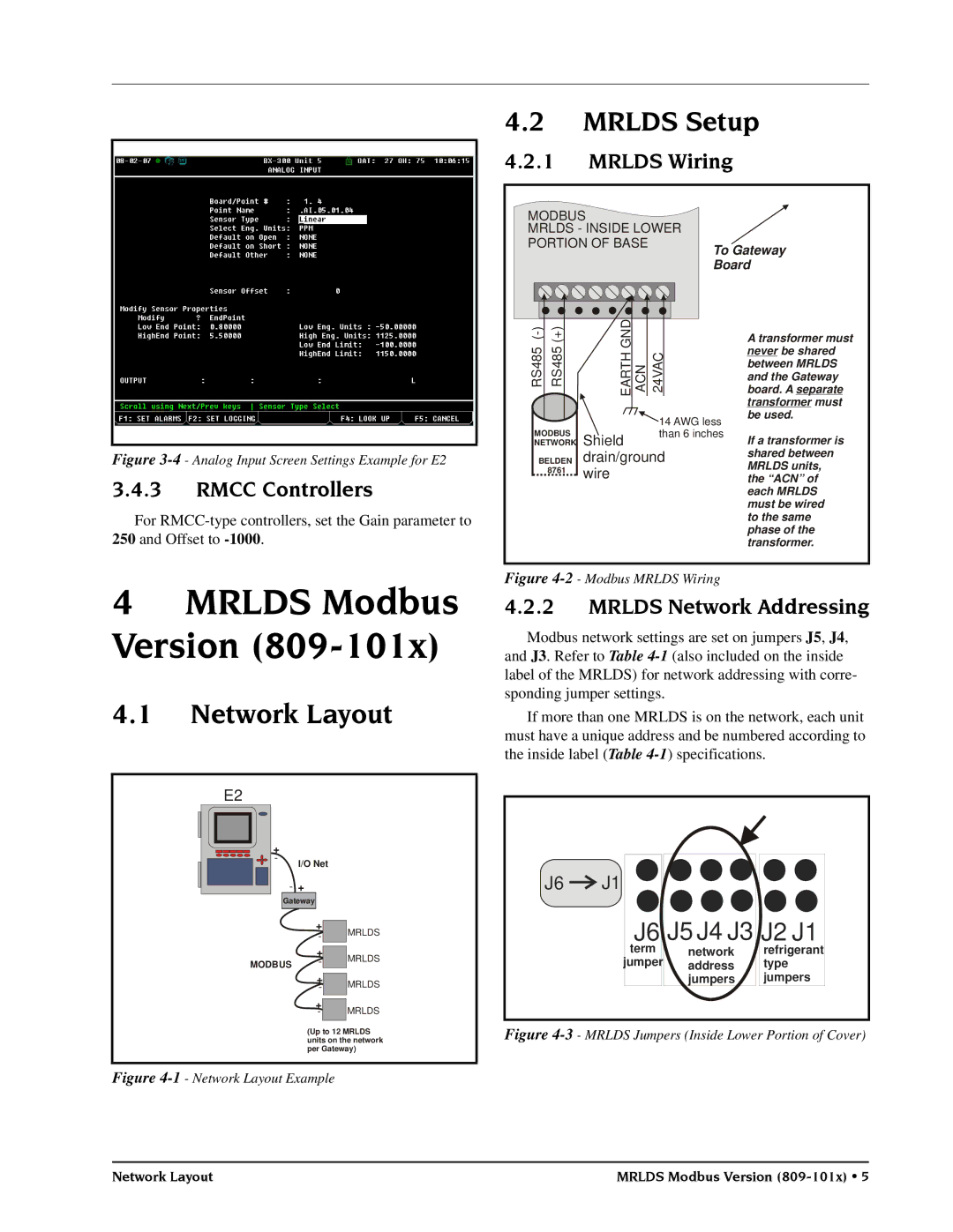
The MRLDS communicates with the E2 controller via a Gateway board connected to the RS485 I/O Network, or via the analog input on a MultiFlex board.
1.1Specifications
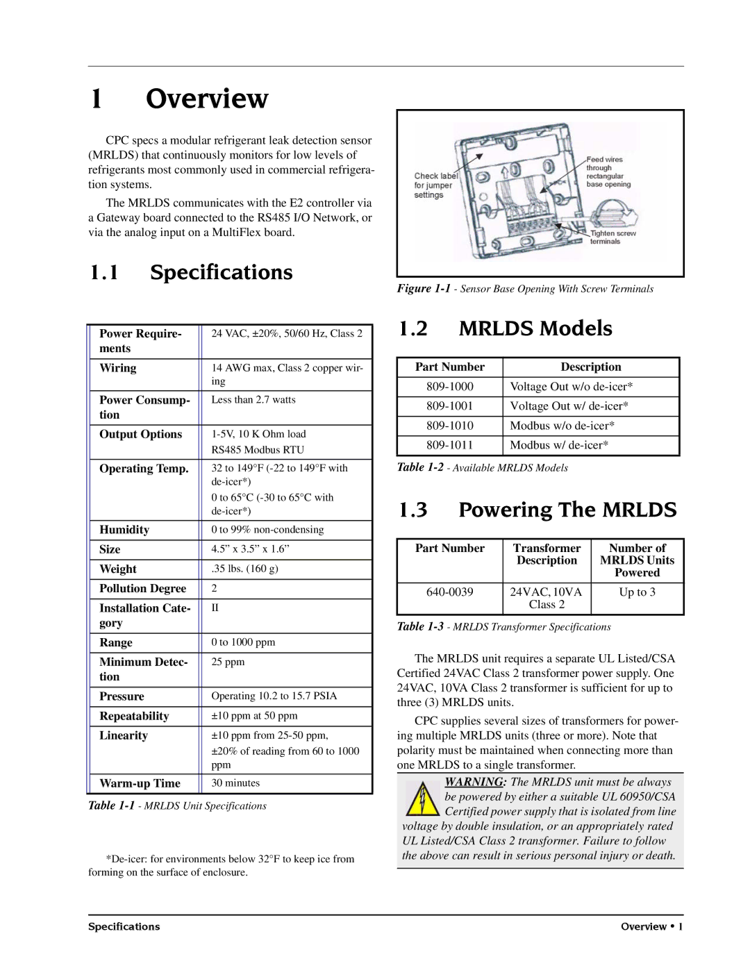
| Power Require- |
| 24 VAC, ±20%, 50/60 Hz, Class 2 |
| ments |
|
|
| Wiring |
| 14 AWG max, Class 2 copper wir- |
|
|
| ing |
| Power Consump- |
| Less than 2.7 watts |
| tion |
|
|
| Output Options |
| |
|
|
| RS485 Modbus RTU |
| Operating Temp. |
| 32 to 149°F |
|
|
| |
|
|
| 0 to 65°C |
|
|
| |
| Humidity |
| 0 to 99% |
| Size |
| 4.5” x 3.5” x 1.6” |
| Weight |
| .35 lbs. (160 g) |
| Pollution Degree |
| 2 |
| Installation Cate- |
| II |
| gory |
|
|
| Range |
| 0 to 1000 ppm |
| Minimum Detec- |
| 25 ppm |
| tion |
|
|
| Pressure |
| Operating 10.2 to 15.7 PSIA |
| Repeatability |
| ±10 ppm at 50 ppm |
| Linearity |
| ±10 ppm from |
|
|
| ±20% of reading from 60 to 1000 |
|
|
| ppm |
|
|
| 30 minutes |
|
|
|
|
Table
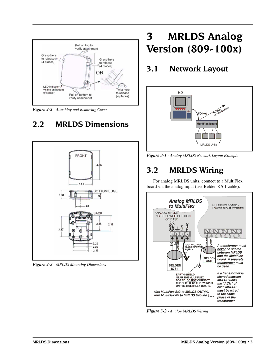
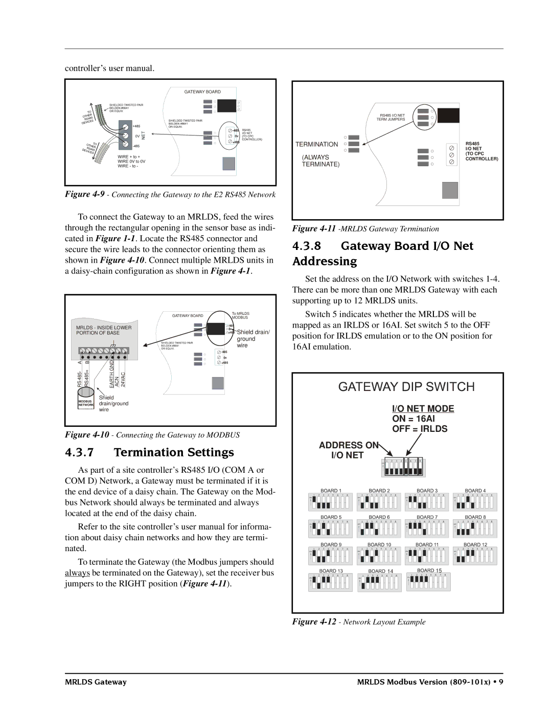
Figure 1-1 - Sensor Base Opening With Screw Terminals
1.2MRLDS Models
Part Number | Description |
|
|
Voltage Out w/o | |
|
|
Voltage Out w/ | |
|
|
Modbus w/o | |
|
|
Modbus w/ | |
|
|
Table
1.3Powering The MRLDS
Part Number | Transformer | Number of |
| Description | MRLDS Units |
|
| Powered |
24VAC, 10VA | Up to 3 | |
| Class 2 |
|
Table | ||
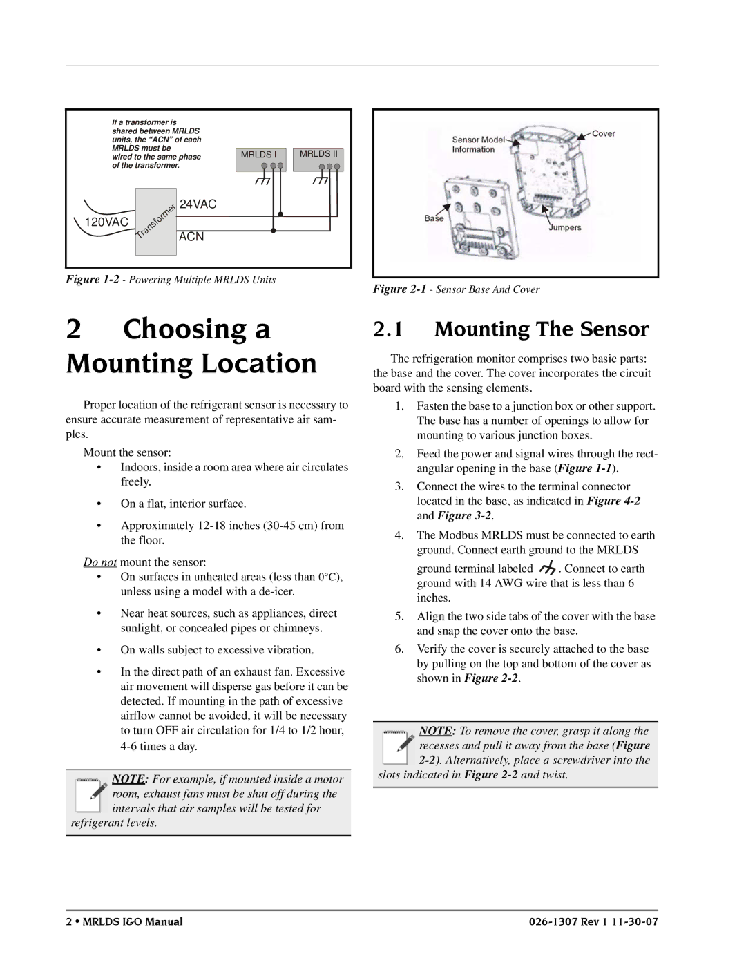
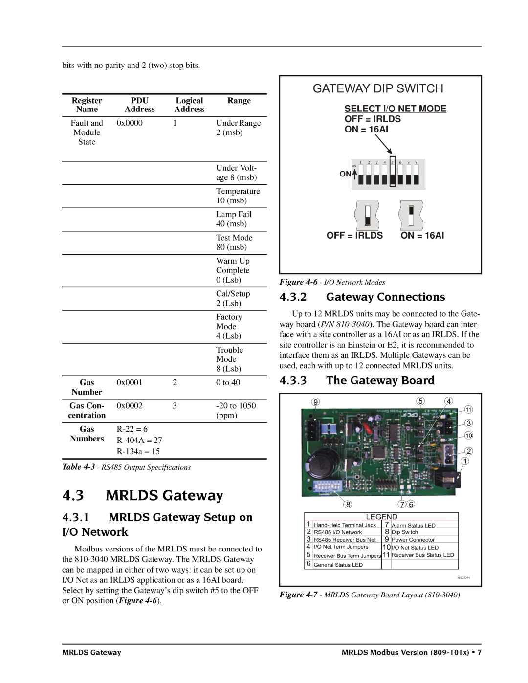
The MRLDS unit requires a separate UL Listed/CSA Certified 24VAC Class 2 transformer power supply. One 24VAC, 10VA Class 2 transformer is sufficient for up to three (3) MRLDS units.
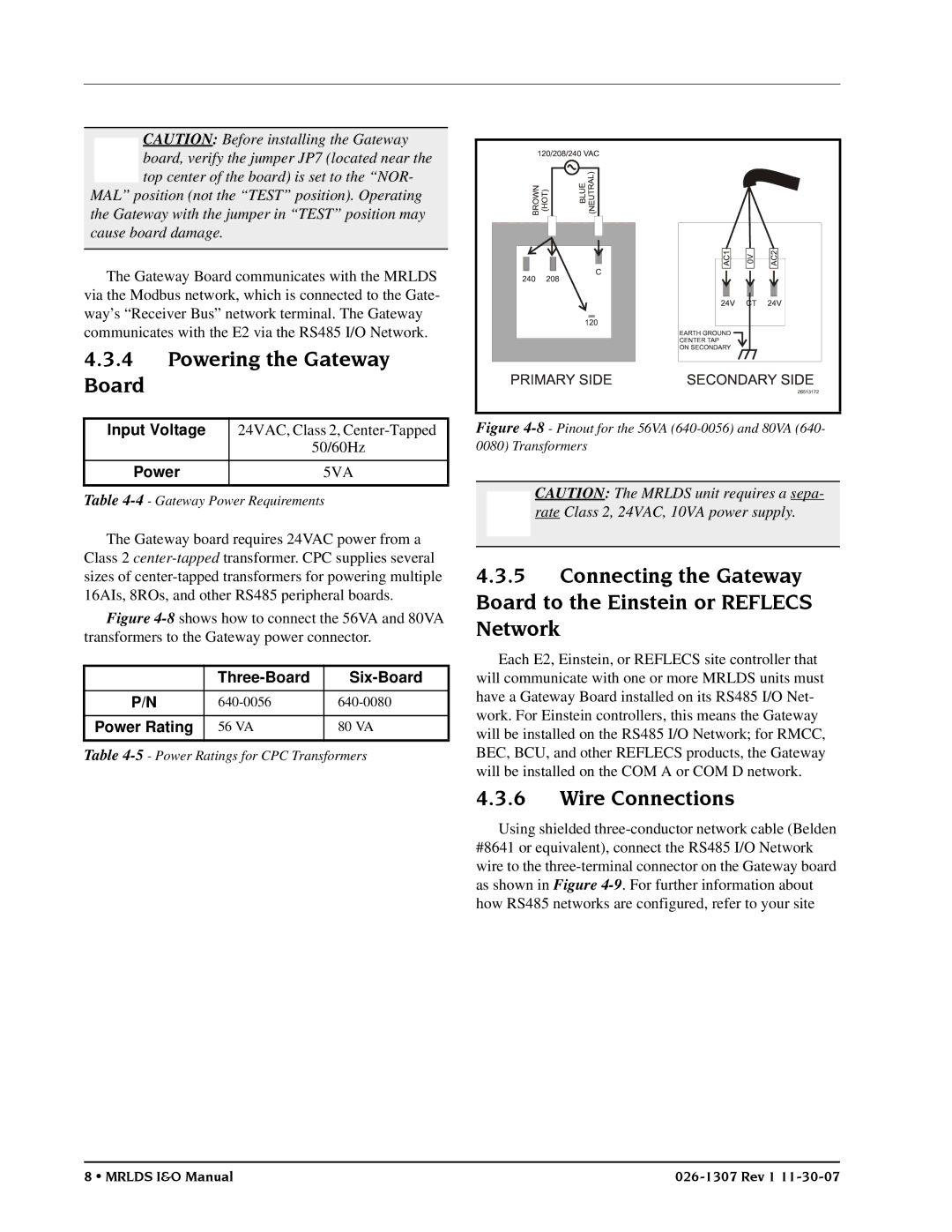
CPC supplies several sizes of transformers for power- ing multiple MRLDS units (three or more). Note that polarity must be maintained when connecting more than one MRLDS to a single transformer.
WARNING: The MRLDS unit must be always be powered by either a suitable UL 60950/CSA Certified power supply that is isolated from line voltage by double insulation, or an appropriately rated
UL Listed/CSA Class 2 transformer. Failure to follow the above can result in serious personal injury or death.
Specifications | Overview • 1 |
