3Com 3015 (3C13615), 3013 (3C13613) manual System Specifications for the Router 3016 and Router

Page 15

Router 3016 and Router 3018 15

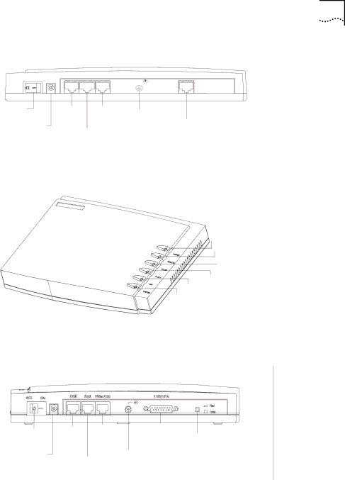
Figure 6 Back Panel of the Router 3016

CON AUX 100METH


CT1/PRI

OFF ON


Power

CON

100M

Grounding

switch

Power

port

Ethernet screw


port

CT1/PRI

input

AUX

port

socket


port


Figure 7 illustrates the Router 3018.

Figure 7 Router 3018

Power LED

Ethernet LED

E1 Link LED

E1 ACT LED

AUX LED

System LED

Figure 8 illustrates the back panel of the Router 3018.

Figure 8 Back Panel of the Router 3018

Power


CON

100M


E1/CE1/PRI

Port impedance


switch

port

Ethernet

port

Power


port Grounding

toggling button


input

AUX

screw


socket port

System Specifications Table 16 lists system specifications for the Router 3016 and Router 3018.

Table 16 System Specifications for the Router 3016 and Router 3018

Item

Router 3016 Description

Router 3018 Description


Fixed ports

1 console port

1 console port


1

10/100 Mbps Ethernet port

1

10/100 Mbps Ethernet port


1

AUX port

1

AUX port


1

CT1/PRI port

1

E1/CE1/PRI port


Button


1

E1/CE1/PRI port impedance


toggling button


Processor

MPC860T 50 MHz


SDRAM

64 MB


Flash memory

8

MB


Image 15
Contents Router 3000 Family Installation Guide 01752-3064 3Com CorporationCampus Drive Marlborough, MAContents T1 Cable Console Cable AUX Cable Ethernet CableText Conventions About this GuideConventions List conventions that are used throughout this guideExamples Router Introducing the Router FamilyRouter 3012 LEDs System Specifications for the RouterLists attributes of the AUX port Console PortLists attributes of the console port AUX PortSynchronous/Asynchronous Serial Port Router 3013Ethernet Port Lists attributes of the Ethernet portRouter 3013 Description Router 3015 Description System Specifications for the Router 3013 and RouterSerial Router 3013 and Router 3015 LEDsEIA/TIA-23 Attributes of Isdn S/T and U Ports Router 3016Isdn S/T and Isdn U Ports Lists attributes of the Isdn S/T and Isdn U portsRouter 3016 Description Router 3018 Description System Specifications for the Router 3016 and RouterT1-ACT/E1-ACT Router 3016 LEDsAttributes of the CT1/PRI Port CT1/PRI and E1/CE1/PRI PortsLists attributes of the CT1/PRI and and E1/CE1/PRI ports Attributes of the Ethernet PortIsdn PRI Installing the Router Static Electricity Temperature and HumidityDust GasesLightning Damage Electromagnetic DischargeBottom of the Router On a Workbench Installing the RouterConnecting WireTo the Console TerminalTo the Ethernet Connecting the Router to the WAN Installing the Router Verifying InstallationInstalling the Router To a Local Console Booting and Configuring RouterConnecting the Router SettingConnection Description Dialog Box Parity None Stop bits Set the following parameters Bits per second 9600 Data bitsHyperTerminal Window Powering on Router Startup ProcessInformation displays on the terminal screen Configuration Online help, available by typing ? at any time Help for the Configuration Maintaining the Router Software MaintenanceXmodem Protocol DownloadingSend File Dialog Box Applications with the copy from Tftp Protocol Creating the Tftp Upgrade ConfigurationProtocol Terminal displays the following menuPress Enter. The following information displays Configuring the RouterUploading Using FTPCreating a Local FTP Upload/Download Configuration Upgrading the ApplicationCreating a Remote FTP Upload/Download Configuration Add the user name and passwordFTP server ready on R3000 at User10.110.10.10none R3000 quit R3000 save Router Chassis HardwaretoolsCover Boot ROM LocationMaintaining the Router Troubleshooting Power LED is OffNothing is Displayed on the Terminal after Power-On Terminal after Power-OnIllegible Characters Display onDescribes the console cable pinouts Console Cable Pinouts Optional Cable SpecificationsConsole Cable AUX CableEthernet Cable Describes the AUX cable pinouts AUX Cable PinoutsThat uses category-5 twisted pair cable, as shown in Figure Crossover Network Cable Pinouts Serial Port CableDescribes crossover network cable pinouts Straight-through Network Cable PinoutsEIA/TIA-232 Maximum Transmission Baud Rate bps Distance m DTE and DCE modeCable Pinouts Typical DTE and DCE24 EIA/TIA-232 DTE Cable Pinout Describes V.24 EIA/TIA-232 DTE cable pinouts24 EIA/TIA-232 DCE illustrates the V.24 DCE cable Describes V.24 EIA/TIA-232 DCE cable pinoutsRTS/CTS CTS/RTS DTR/DSR LL/DCD DCE Cable Pinouts illustrates the V.35 DCE cable DB-50 Signal Signal DirectionDTE Cable Pinouts illustrates the V.35 DTE cable Describes V.35 DTE cable pinoutsSignal DB-50 Direction Describes V.35 DCE cable pinouts 35 DCE cable PinoutsDTE Cable Pinouts illustrates the X.21 DTE cable 21 DTE Cable Pinouts Describes X.21 DTE cable pinoutsDCE Cable Pinouts illustrates the X.21 DCE cable Describes X.21 DCE cable pinoutsDescribes EIA/TIA-449 DTE cable pinouts DB50 Signal Signal Direction DB37EIA/TIA-449 DTE Cable illustrates the EIA/TIA-449 DTE cable PinoutsEIA/TIA-449 DCE Cable illustrates the EIA/TIA-449 DCE cable EIA/TIA-449 DCE Cable AssemblyEIA-530 DTE Cable Pinouts DB50 Signal Signal Direction DB25EIA-530 DTE Cable illustrates the EIA-530 DTE cable Describes EIA-530 DTE cable pinoutsDescribes Isdn S/T port cable pinouts T1 CableIsdn BRI Cables Describes T1 cable pinoutsIsdn U Port Cable Obtaining Support for Your Router Contact Us Telephone TechnicalSupport and Repair US and Canada Telephone Technical Support and Repair Latin America Telephone Technical Support and RepairAppendix B Obtaining Support for Your Router