MAINTENANCE
REMOVING THE CHUCK
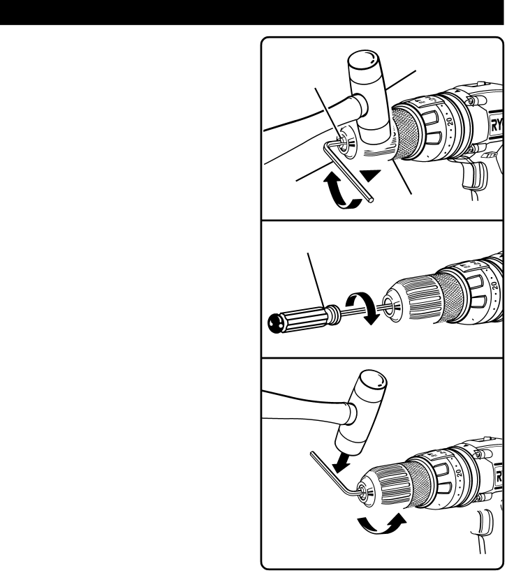
See Figures 16, 17, and 18.
Follow these steps to remove the chuck.
■Lock the trigger switch by placing the rotation selector in the center position.
■Insert a 5/16 inch or larger hex key wrench into the chuck of the drill and tighten the chuck jaws securely.
■Tap the hex key wrench sharply with a mallet in a clockwise direction. This will loosen the screw in the chuck for easy removal.
■Open the chuck jaws and remove the hex key wrench.
■Remove the chuck screw by turning it in a clockwise direction.
Note: The screw has left hand threads.
■Insert the hex key wrench in the chuck and tighten the chuck jaws securely.
■Tap sharply with a mallet in a counterclockwise direc- tion. This will loosen chuck on the spindle. It can now be unscrewed by hand.
TIGHTENING THE CHUCK
The chuck may become loose on the spindle and begin to shake when using the drill. Also, the chuck screw may become loose causing the chuck jaws to bind and prevent them from closing.
Follow these steps to tighten the chuck.
■Lock the trigger switch by placing the rotation selector in center position.
■Open the chuck jaws.
■Insert the hex key wrench into the chuck and tighten the chuck jaws securely.
■Tap the hex key wrench sharply with a mallet in a clockwise direction. This will tighten chuck on the spindle.
■Open the chuck jaws and remove the hex key wrench.
■Tighten the chuck screw.
Note: The chuck screw has left hand threads.
MALLET
CHUCK JAWS

![]()
![]()
![]()
![]()
![]() 15
15
HEX KEY
KEYLESS CHUCK
Fig. 16
SCREWDRIVER

![]()
![]()
![]() 15
15 ![]()
![]()
Fig. 17

![]()
![]()
![]() 15
15 ![]()
![]()
![]()
Fig. 18
Page 18