SECTION 2: CIRCUIT REQUIREMENTS
110V Operation
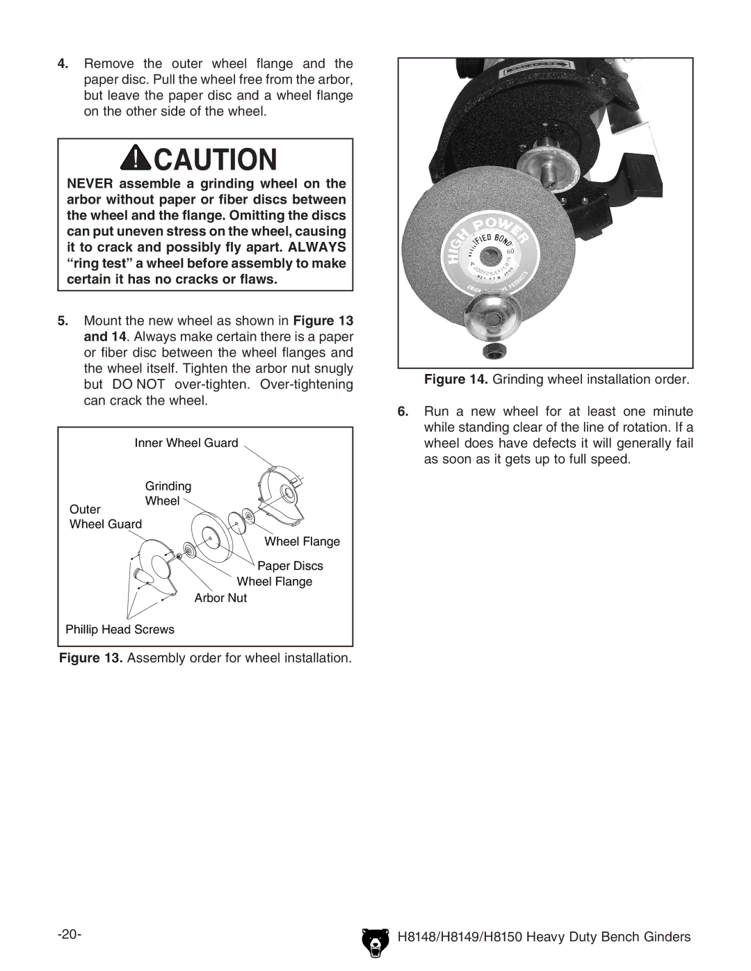
Serious personal injury could occur if you connect the machine to the power source before you have completed the set up pro- cess. DO NOT connect the machine to the power source until instructed to do so.
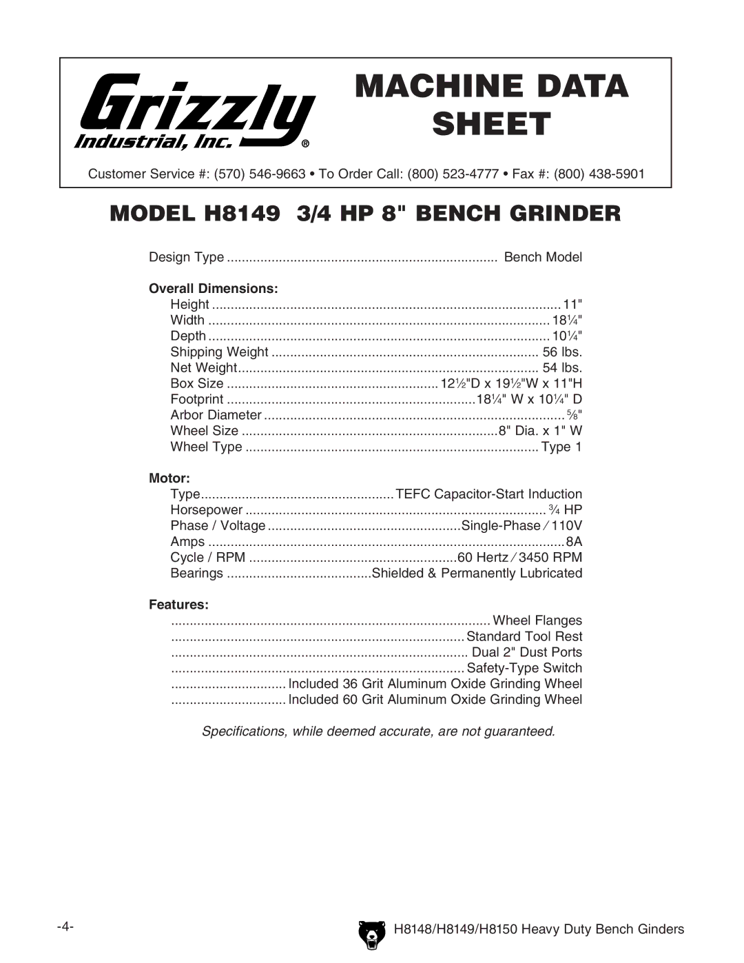
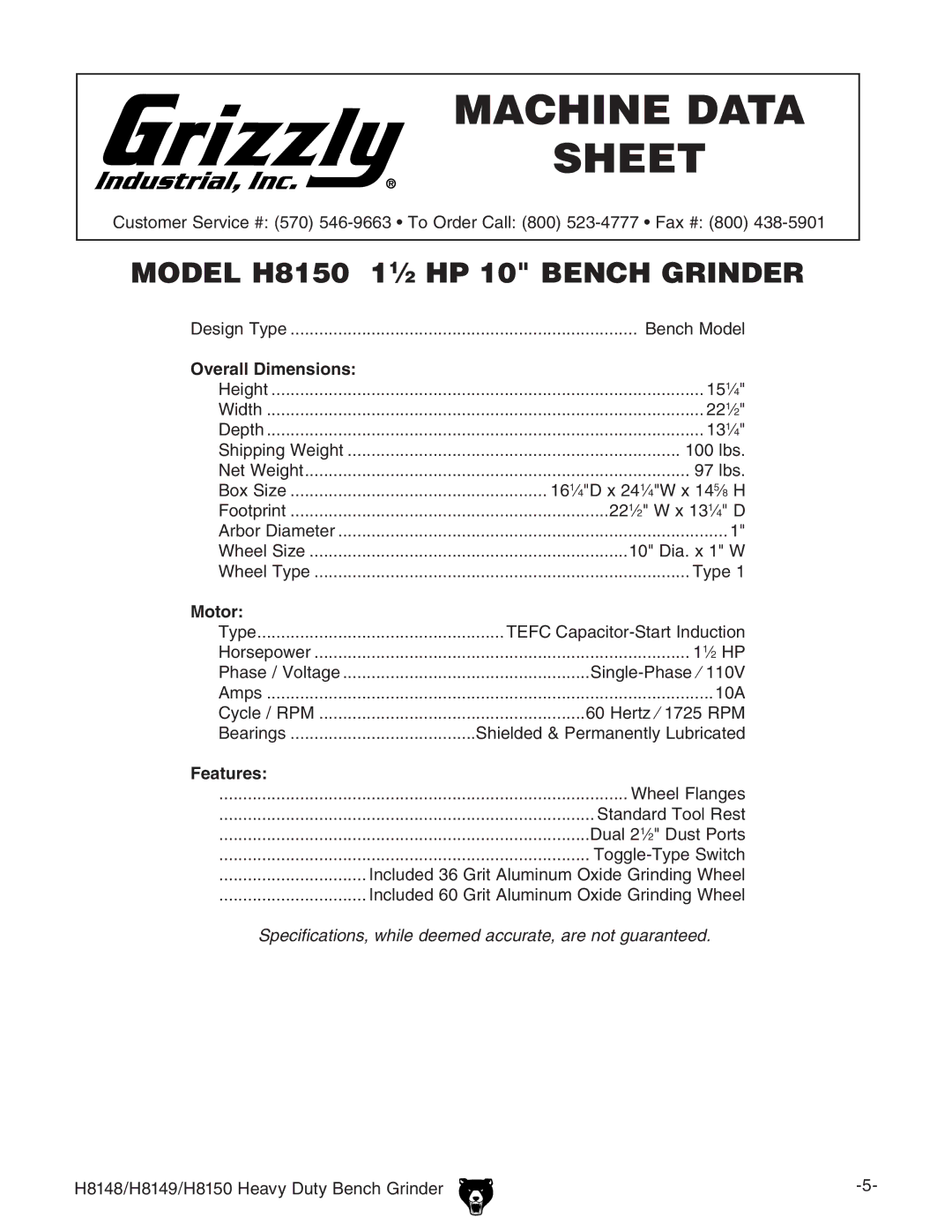
Amperage Draw
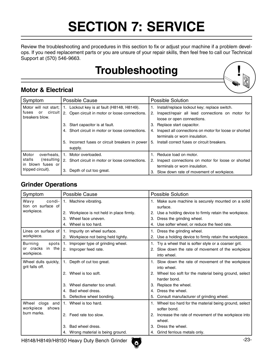
The Model H8148/H8149/H8150 motor draws the following amps under maximum load:
Motor Draw (H8148) | ................................ 5 | Amps |
Motor Draw (H8149) | ................................8 | Amps |
Motor Draw (H8150) | .............................. 10 | Amps |
Circuit Recommendations
We recommend connecting your machine to a dedicated and grounded circuit that is rated for the amperage given below. Never replace a circuit breaker on an existing circuit with one of higher amperage without consulting a qualified electri- cian to ensure compliance with wiring codes. If you are unsure about the wiring codes in your area or you plan to connect your machine to a shared circuit, consult a qualified electrician.
110V Circuit (H8148/H8149/H8150)...... 15 Amps
Plug/Receptacle Type
Included Plug Type | NEMA |
Figure 2. Typical type |
Electrocution or fire could result if this machine is not grounded correctly or if your electrical configu- ration does not comply with local and state codes. Ensure compliance by checking with a qualified electrician!
This machine must have a ground prong in the plug to help ensure that it is grounded. DO NOT remove ground prong from plug to fit into a
Extension Cords
We do not recommend the use of extension cords, but if you find it absolutely necessary:
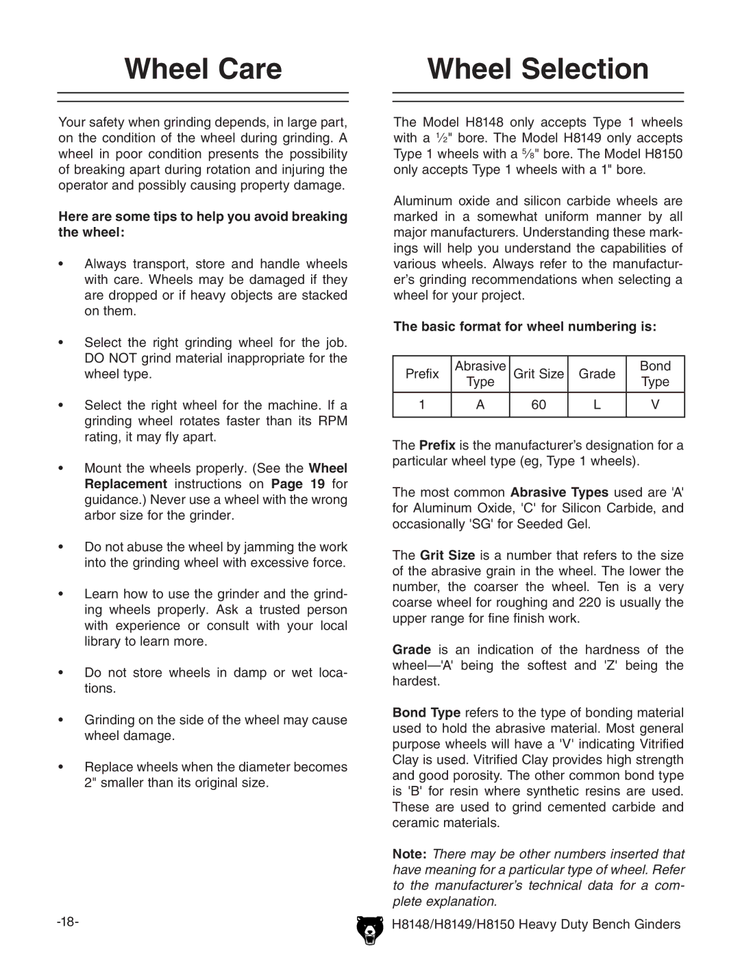
•Use at least a 14 gauge cord that does not exceed 50 feet in length!
•The extension cord must also contain a ground wire and plug pin.
•A qualified electrician MUST size cords over 50 feet long to prevent motor damage.

