HP AR 18 Router manual Installation Manual

Page 35

Installation Manual

Chapter 3 Starting and Maintaining

H3C AR 18-2X Series Routers

the Router

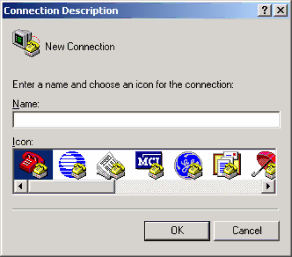
The HyperTerminal window displays the Connection Description dialog box, as shown in Figure 3-2.

Figure 3-2Setting up a new connection

Step 2: Enter the name of the new connection in the Name field and click <OK>. The dialog box, as shown in Figure 3-3,displays.

Step 3: Select the serial port to be used from the Connect Using dropdown menu. The serial port must be the same port connected by the console cable.

3-2

Image 35
Contents H3C AR 18-2X Series Routers Installation Manual Technical Support About This Manual Manual ContentOrganization Chapter ContentsConvention Description Boldface ConventionsConvention Description II. GUI conventionsTable of Contents Introduction Product OverviewAppearance Hardware Features of the ARHardware Features of the AR Sdram II. System specificationsAttribute Description III. LEDsIV. Interface attributes 10/100BASE-T Attribute3Front view of the AR II. System specifications LAN1/LAN2/L 5Front view of the AR 18-22-8/18-22S-8 Hardware Features of the AR 18-22-8/18-22S-8AR 18-22S-8 LAN1/LAN 7Front view of the AR 18-23-1/18-23S-1 Hardware Features of the AR 18-23-1/18-23S-1AR 18-23S-1 ETH0 LINK/ACT Connecting the Router to a Console Terminal Safety Precautions Installing the RouterPlacing the Router on a Tabletop/Workbench Installing the RouterMounting the Router on a Vertical Surface Installing the Router in a Rack 2AR 18-2X installation in a rack Connecting the Ground WireII. Connecting the AC-input power cord Connecting the Power CordAC-input power supply Console cable Connecting the Router to a Console TerminalII. Connecting the console cable Ethernet cable Connecting the Router to LANII. Connecting an Ethernet cable Verifying InstallationInstallation Manual Starting up the Router Starting up the Router Setting up a Configuration EnvironmentConnecting the router to a console terminal II. Setting terminal parametersInstallation Manual Installation Manual Installation Manual 5Setting the terminal type Powering on the RouterMaintaining the Router Boot Menu 8 MB Flash Is InstalledPlease input Boot Rom password = clear field Installation Manual Boot Menu 16 MB Flash Is Installed Installation Manual Boot file File name File type =MAIN B=BACKUP S=SECURE Set this file as Main Backup Exit Enter your choice1-3 Installation Manual Upgrading an application program Upgrading Programs through XModemDownloading ... Ccccc Installation Manual III. Upgrading the extended segment of the Boot ROM program II. Upgrading the Boot Rom programWriting to FLASH.Please wait...#### Upgrading Boot ROM Through Tftp Upgrading Boot ROM at CLIH3C tftp 1.1.1.1 get bootromfull II. Upgrading Boot ROM Through FTP Installation Manual Upgrading Application Programs with NET Installation Manual Host inet h Press Enter as prompted to have the router reboot Troubleshooting Solution Troubleshooting the Power SystemTroubleshooting the Configuration System SymptomsSymptoms Recovering/Replacing a Lost Boot Rom Password
Related manuals
Manual 3 pages 18.26 Kb