Teledyne EHE warranty 4G. Combustion Condensate, 4F-3b. Flow in Heater and Vent

Page 30

Page 28

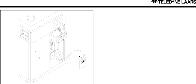
Figure 38. Collector Pressure Measurement

Correct any such problems and verify normal operation by returning to the venturi system checkout procedures.

Pressure readings will be less if the heater is located at an elevation significantly above sea level.

4F-3b. Flow in Heater and Vent

If the venturi inlet pressure reading is normal (or less than normal), flow may be blocked within the heater or in the exhaust venting, or the combustion blower may be operating below standard. To evaluate this, connect the negative side of the manometer to the collector pressure tap, as shown in Figure 38, leaving the positive side open to ambient (This requires a pressure tap with a 1/4" NPT thread). When the heater is operating, the pressure at this location should be about 3.5 ± 0.5" WC less than ambient for a model 220 and 2.8 ± 0.5" WC less than ambient for a model

350.If a greater reading is observed (i.e. more negative), flow is restricted within the heater, most likely at the burner or the heat exchanger. If the reading is substantially less (i.e. less negative), the combustion blower is not operating properly or flow is blocked after the blower, possibly in the vent. Correct any such problems and verify normal operation by returning to the venturi system checkout procedures.

Pressure readings will be less if the heater is located at an elevation significantly above sea level.

4F-4. Fuel Gas Type and Gas Orifice Size

The Hi-E2venturi combustion system requires only a gas orifice change to change from natural to propane gas or vice-versa. Required venturi system and gas pressures are the same for either gas. Required gas orifices are listed in the replacement parts list. Teledyne Laars configures its heaters for natural gas with 0.60 specific gravity and 1035 Btu/Ft3 or for propane gas with 1.52 specific gravity and 2500 Btu/ Ft3. Consult your Teledyne Laars representative if the available gas is substantially different.

4F-5. High Elevation Operation

The venturi combustion flow system completely compensates for installation at elevations other than sea level. Gas orifice changes are not necessary. Unlike conventional systems with open type burners and positive pressure regulators, the gas orifice differential pressure is created by the air flow, and it is automatically reduced when air density decreased. A Hi-E2 heater commissioned at sea level will operate at nearly the same air/gas mixture when operated at higher elevation. Its firing rate will decrease about 3% per 1000 feet due to the barometric pressure change.

In servicing a Hi-E2 heater at high elevation be aware that the input will be naturally reduced by this amount and that the differential pressures, as discussed in prior sections, will also be reduced. Pressure readings at various elevations will be approximately as follows:

Elevation

Gas Orifice

Unfired Venturi

Ft (m)

Differential

Differential

Sea Level 4.0" (102 mm) WC

4.7" (119 mm) WC

2000

(610)

3.7 (94)

4.3 (109)

4000

(1220)

3.4 (86)

4.0 (102)

6000 (1830

3.2 (81)

3.7 (94)

8000

(2440)

2.9 (74)

3.5 (89)

10000 (3050)

2.7 (69)

3.2 (81)


The gas pressure offset is determined by the regulator spring adjustment, not air density. It is not affected by elevation change.

4G. Combustion Condensate

The condensate disposal system of the Hi-E2pool heater is quite simple, but must be properly installed and maintained. See the installation instructions for information on correct tubing installation. Condensate drainage should be observed routinely and if necessary, the flow-ways should be cleaned.

In normal operation, condensate drains from the condensate collector behind the combustion fan. A 5/8" I.D. drain tube conducts this water into the condensate trap/neutralizer, where a “water seal” prevents room air from being pulled into the system. A smaller amount of condensate may drain from the vent duct and blower. The water seal of the trap prevents vent gases from being discharged into the room. See Figures 11 and 12 in the Condensate Disposal section of the installation instructions.

During start-up, condensate from the collector cannot reach the trap unless the water seal is established. This can be done by pouring water into the trap. The heater will self-prime by driving water into the vent outlet, from which it will eventually drain into the trap. However, it is better to avoid this by manually priming the trap.

Image 30
Contents Installation Hi-E2 Model EHE Gas-Fired Pool Spa Heater Table of Contents Installation Instructions General Information2E. Outdoor Installation 2B. Heater Assembly and Preparation2D. Installation Clearances Installation at High Elevation2G-1. Preparation of Heater For Indoor Installation 2F. Outdoor Shelter Installation Canada2G. Indoor Installation United States2G-3a. Connection of Combustion Air Pipe 2G-2. Combustion Air Requirements for One-Pipe Installation2G-3. Two-Pipe Installation Direct Vent 2G-3b. Piping MaterialsInstallation 2G-3d. Combustion Air and Vent Pipe2G-3c. Size and Length of Combustion Air and Vent Piping Indoor Vent Connection, Hi-E2 Pool Heater 2G-3e. Room Ventilation 2H. Condensate Disposal2I. Gas Supply and Piping High Elevation 60Hz2J-3. Auxiliary Time Clock Wiring 2J. Electric Wiring2J-1. Electrical Power 2J-2. Bonding2K. Water Piping 2K-1. Reversal of Heater Water Connections2K-3. Connections at Heater 2K-4. Pressure Relief Valve 2K-5. Automatic Chlorinators Chemical Feeders2L. Start-up and Adjustment 2L-1. Normal Operation2L-3. Condensate 2L-5. Adjustment of Water Pressure Switch2L-2. Start-up 2L-4. Gas Pressure2L-6. Water Temperature Rise Operating Instructions3A. Start-Up Procedure 3B. Temperature Controls3C. Lighting and Shutdown 3D. Water Chemistry3F. Swimming Pool Energy Savings Tips 3E. Spa/Hot Tub Safety Rules3D-2d. Testing 3D-2c. Corrosion3G-1. Spring and Fall Operation 3G. Seasonal Care3H. Periodic Inspection 3G-2. WinterizingMaintenance and Service 4A. General3H-2. Professional Inspection 4B. Induced-Draft Combustion System 4C. Heater Components and Their Operation4E. Electrical Trouble Shooting 4E-1 V Electrical Power Supply4D. Combustion Air Filter 4E-2. Control Circuit Trouble Shooting 4E-2a. Transformer4E-2b. Fuse 4E-2e. Water Pressure Switch 4E-2c. Fireman Switch and External Interlocks4E-2d. Limit Switches 4E-2f. Temperature Control4F. Venturi Combustion Flow System 4F-2b. Gas Pressure Offset 4F-2. Venturi System Checkout4F-2a. Unfired Venturi Differential Pressure 4F-2c. Gas Orifice Differential4F-3. Air Flow Investigation 4F-3a. Combustion Air Flow4F-4. Fuel Gas Type and Gas Orifice Size 4G. Combustion Condensate4F-3b. Flow in Heater and Vent 4F-5. High Elevation OperationCapacities and Dimensions 4H. Major Component Service5A. General Information Replacement Parts 6A. Parts ListExploded View of the Hi-E2 Limited Warranty