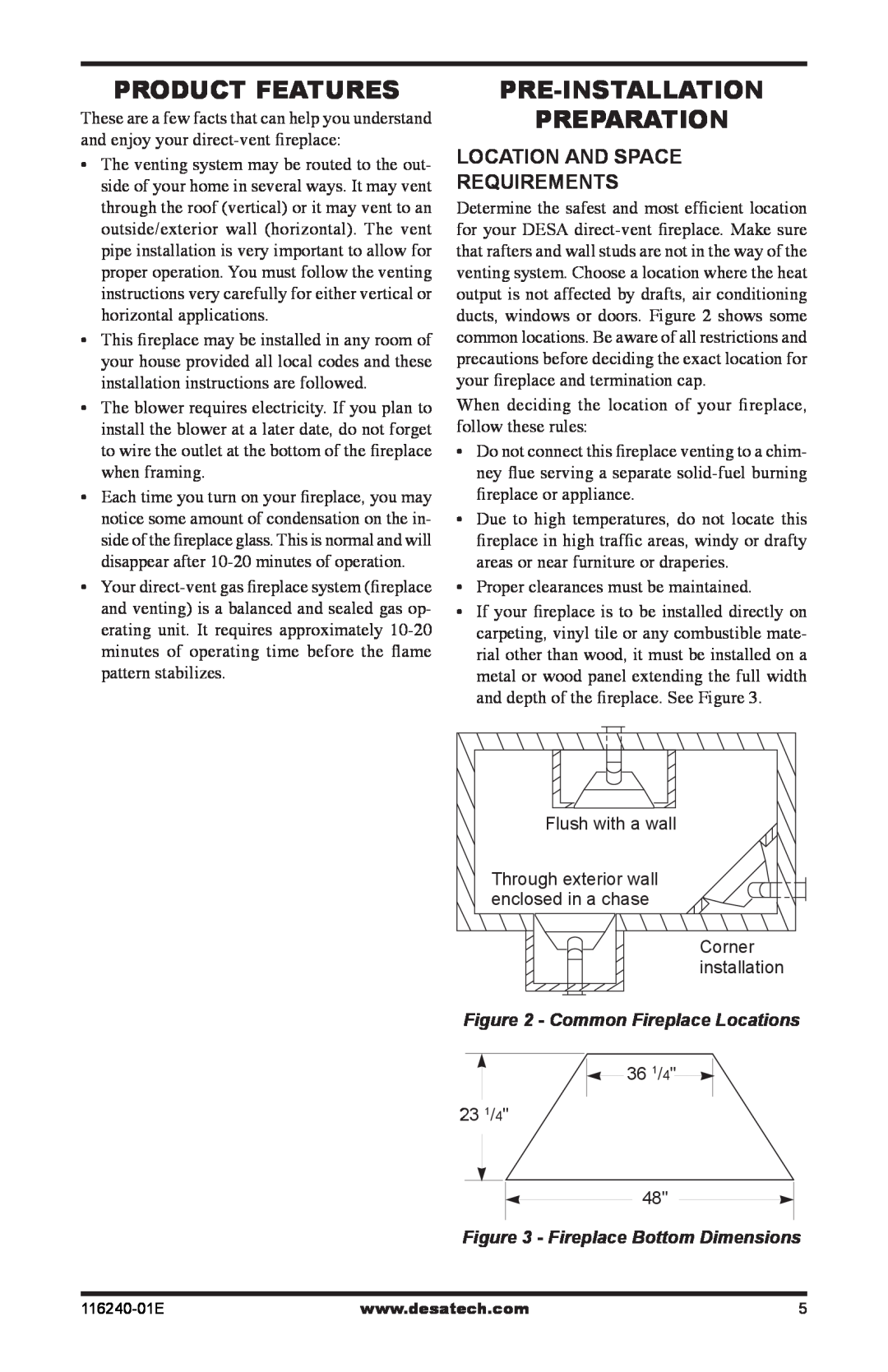
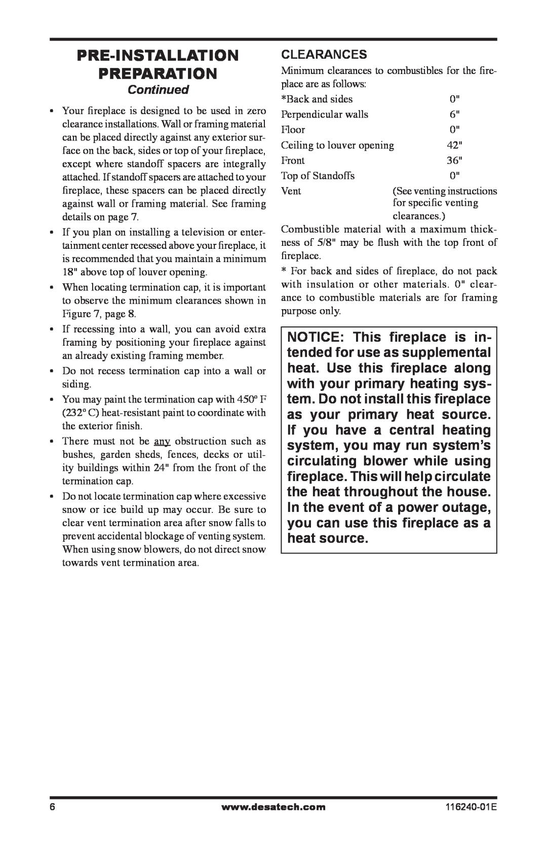
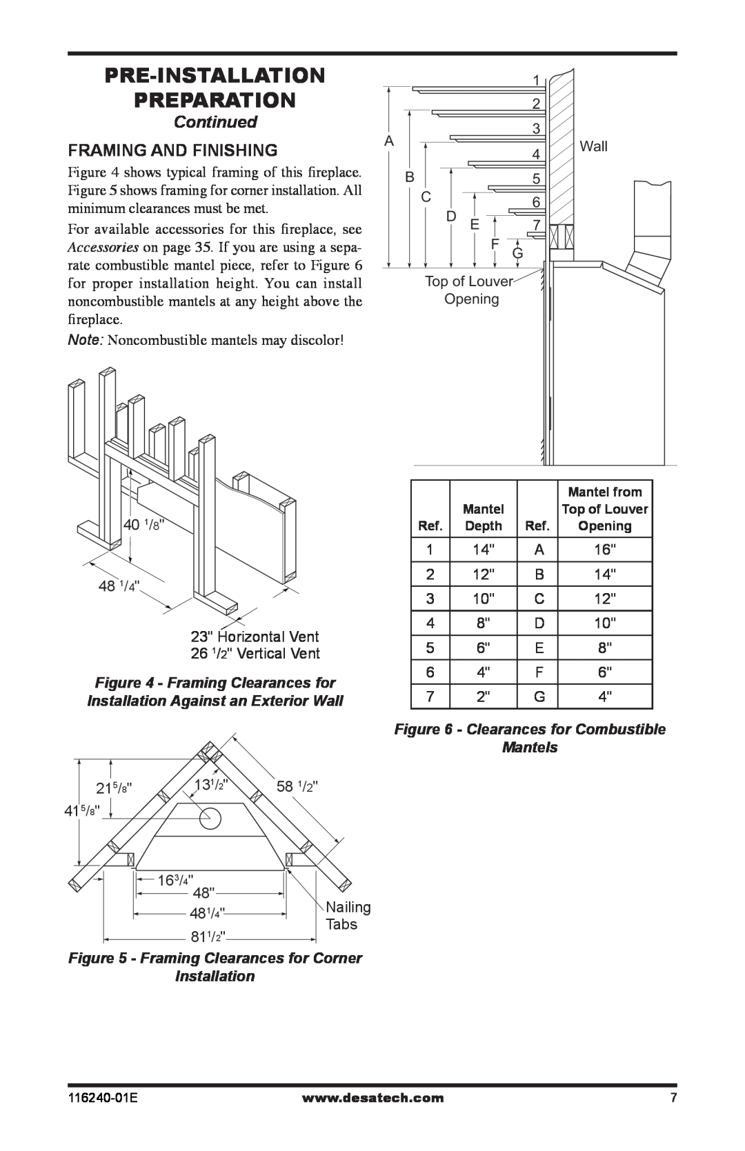
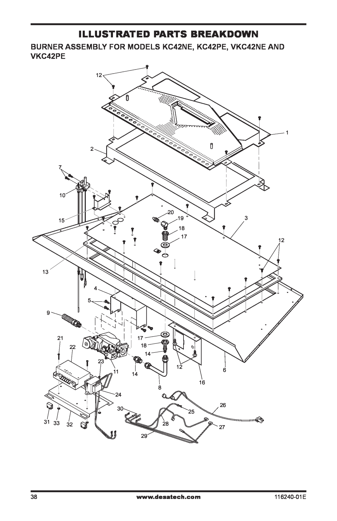
Desa (V)KC42PE installation manual Continued, Vertical Venting, Configuration Using Two 90 Elbows

Page 16
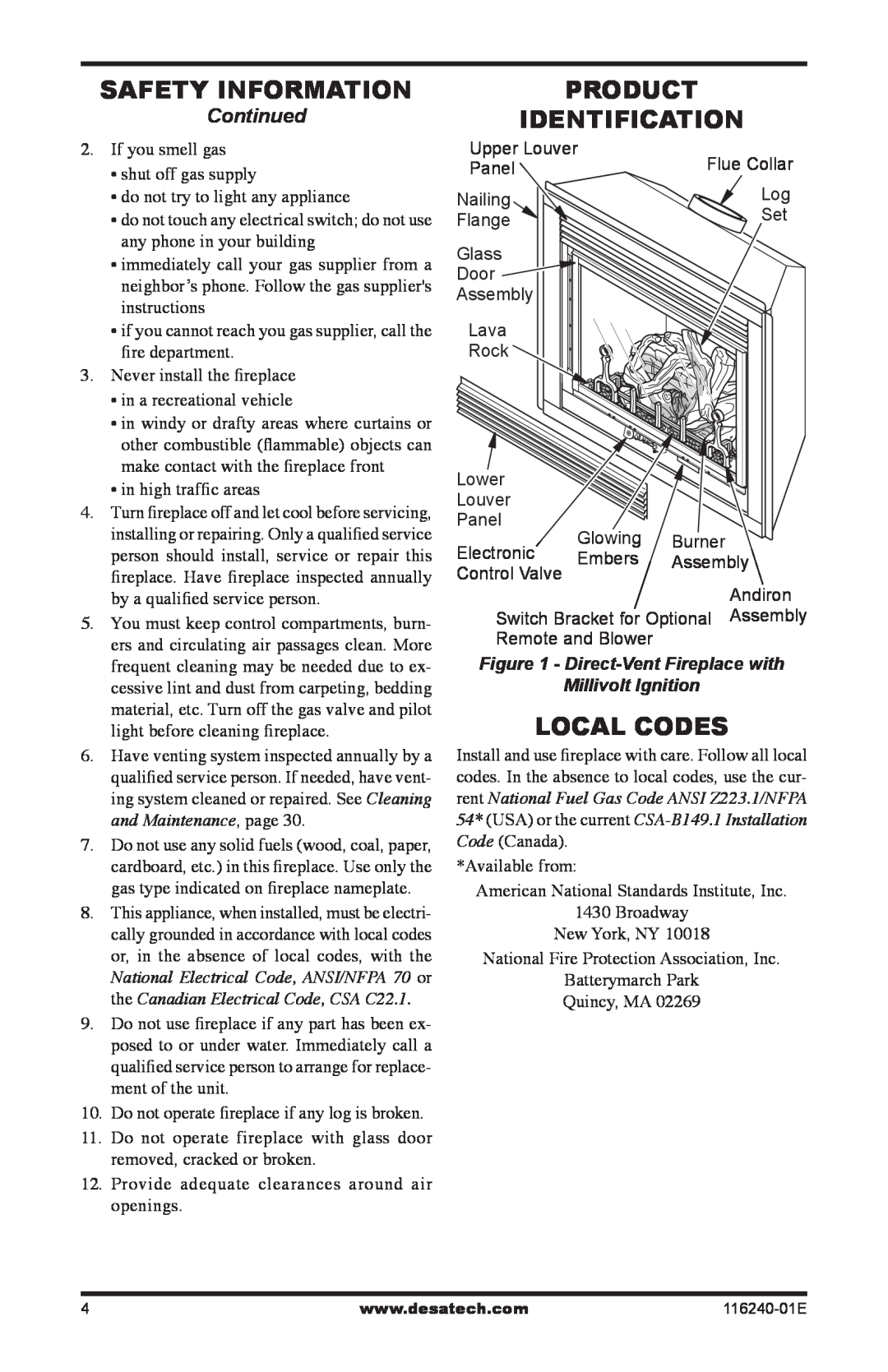
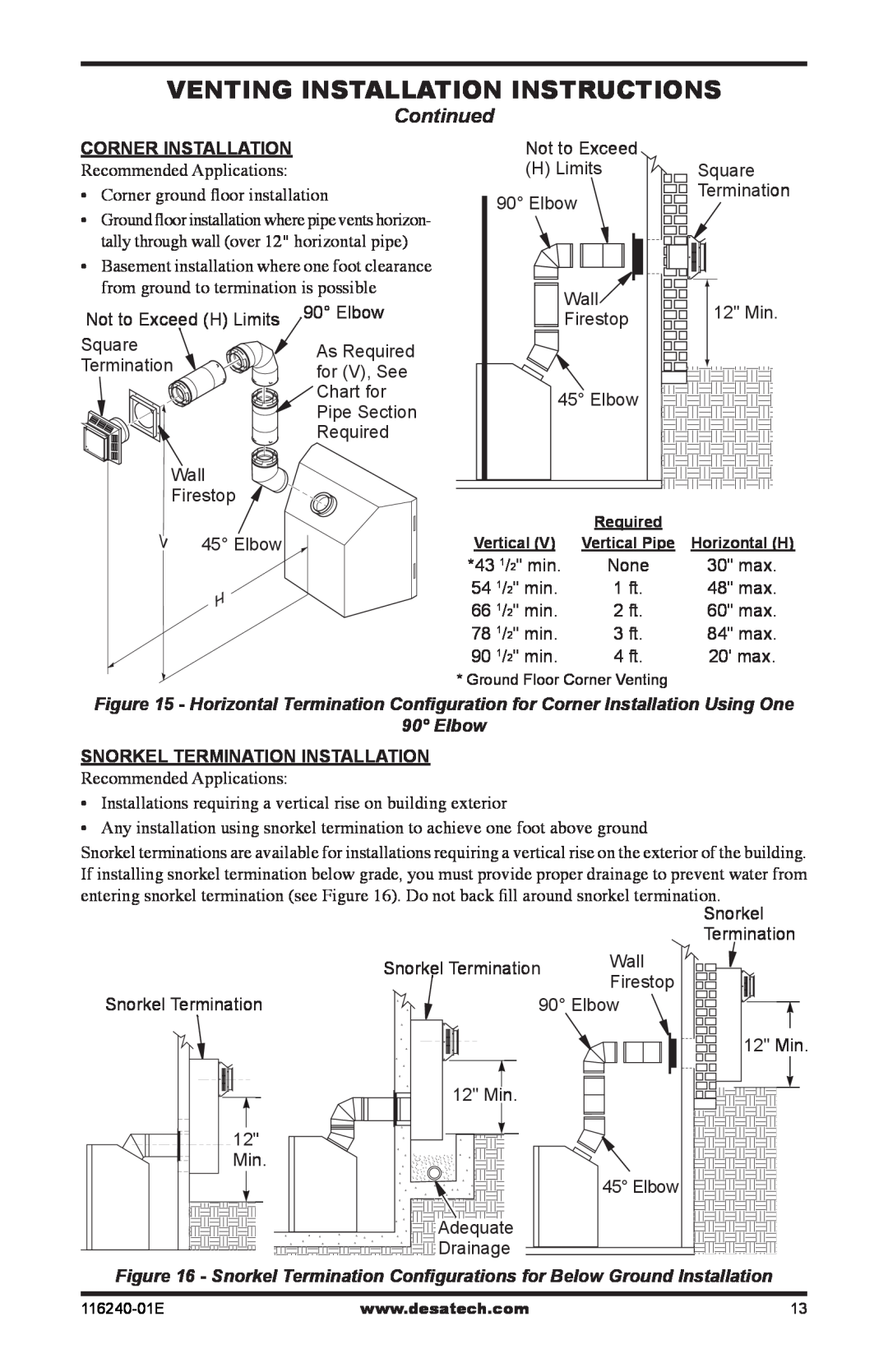
Figure 21 - Vertical Venting

Venting Installation

instructions

Continued

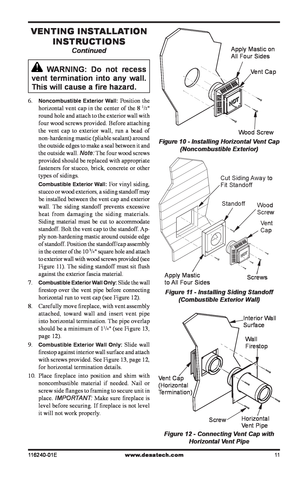
5.Place the flashing over the pipe section(s) extending through the roof. Secure the base of the flashing to the roof and framing with roof- ing nails. Be sure roofing material overlaps the top edge of the flashing as shown in Figure 19, page 15. There must be a 1" clearance from the vent pipe to combustible materials.

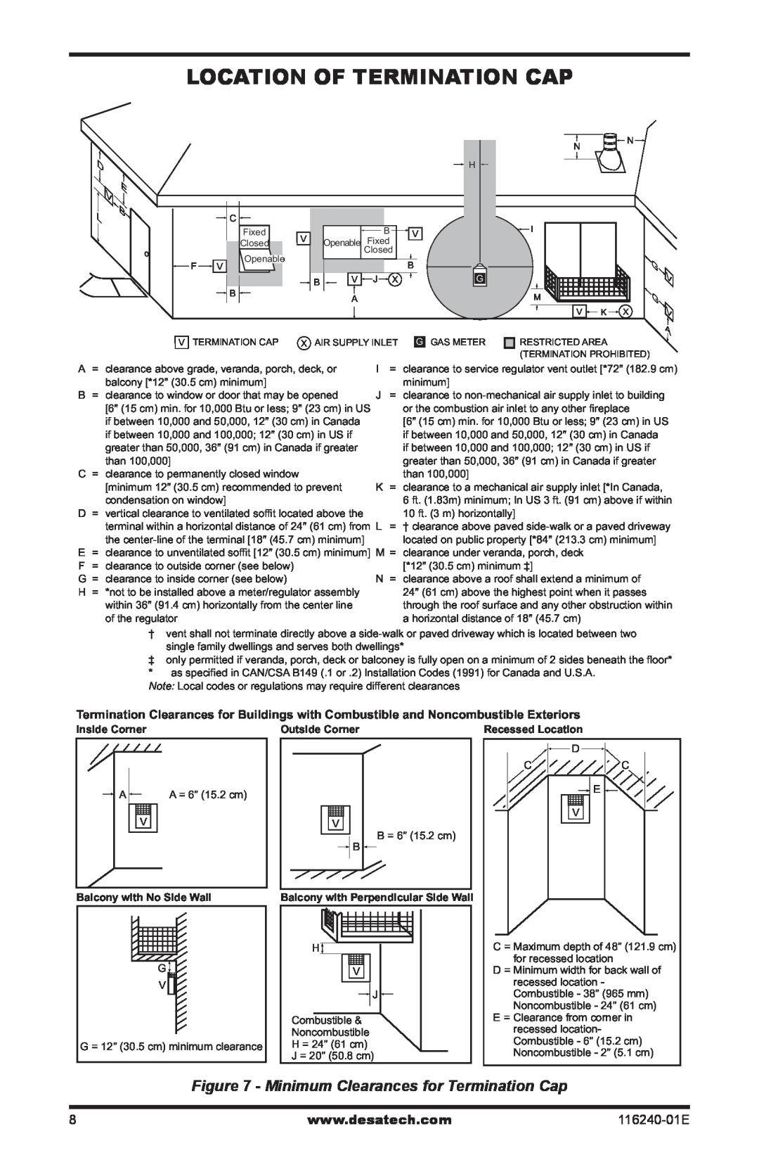
6.Continue to add pipe sections until the height of the vent cap meets the minimum building code requirements described in Figure 7 on page 8. Note: You must increase vent height for steep roof pitches. Nearby trees, adjoining rooflines, steep pitched roofs and other similar factors may cause poor draft or down-drafting in high winds. Increasing the vent height may solve this problem.

7.Twist-lock the vent cap onto the last section of vent pipe.

Note: If the vent pipe passes through any occupied areas above the first floor, including storage spaces and closets, you must enclose pipe. You may frame and sheetrock the enclosure with standard construction material. Make sure and meet the minimum allowable clearances to combustibles. Do not fill any of the required air spaces with insulation.

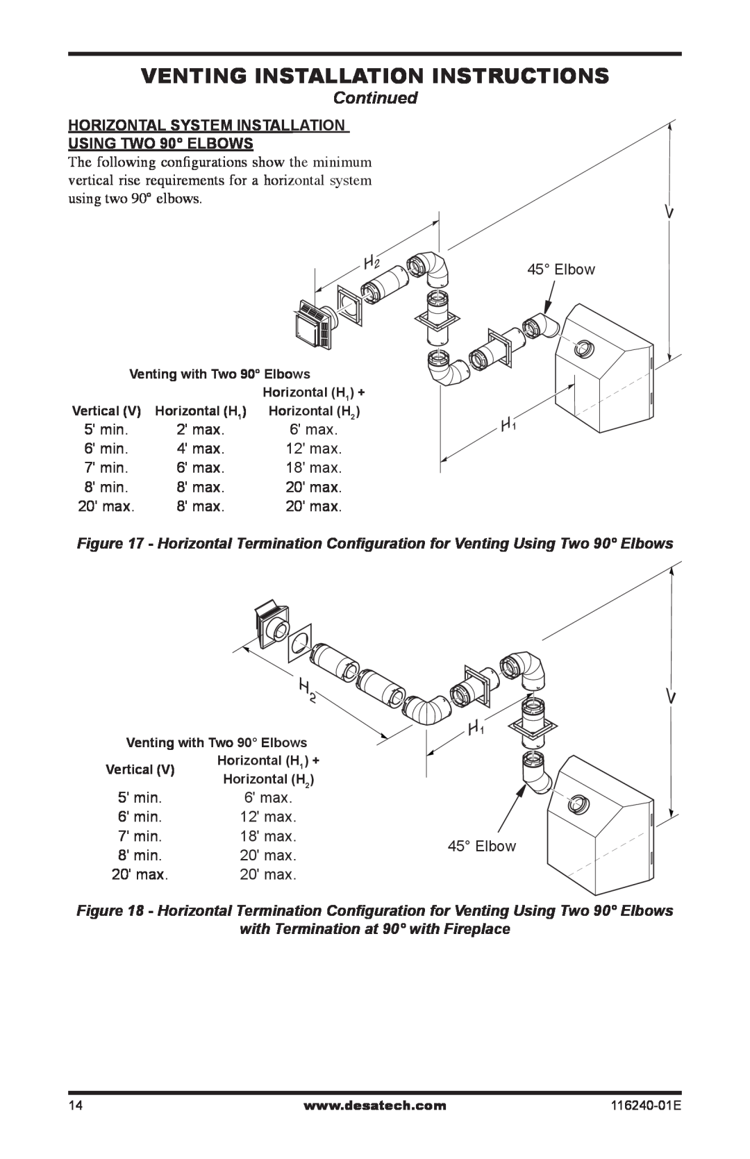
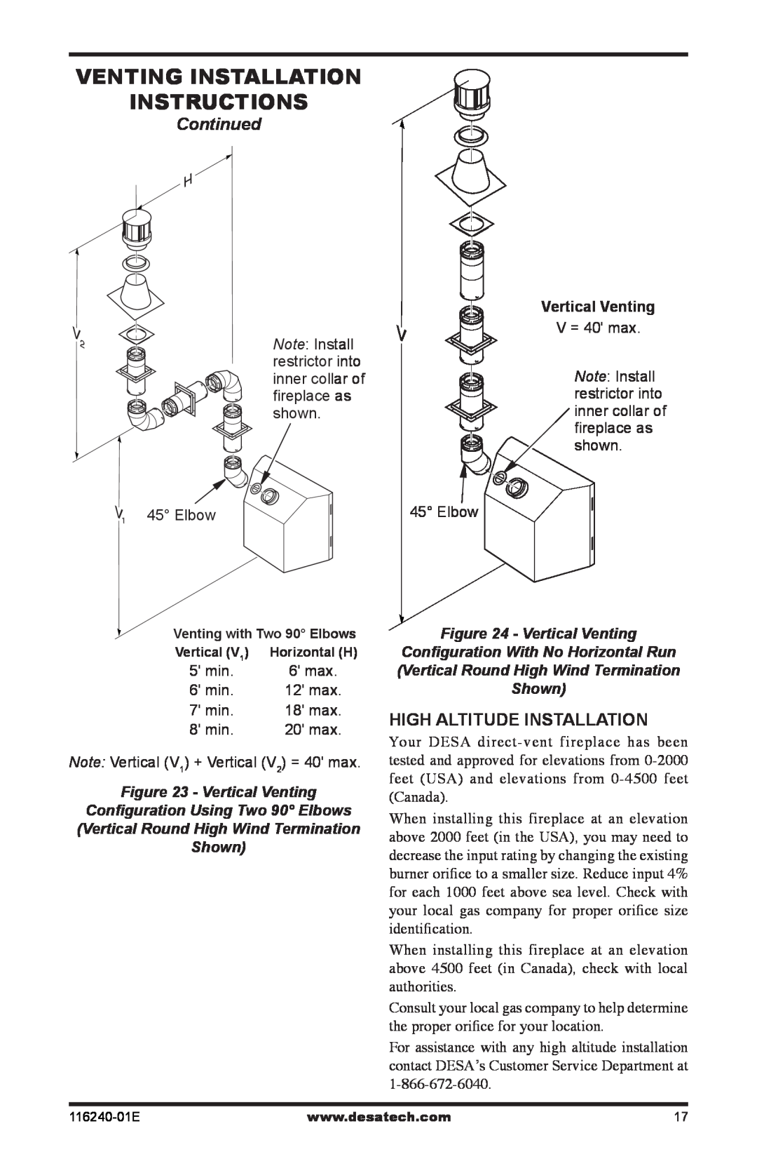
Vertical Termination Configurations Figures 21 through 24 show four different con- figurations for vertical termination.

Venting with Two 90° Elbows

Horizontal (H1) +

Vertical (V) Horizontal (H2)

5' min.

2' max.

6' min.

4' max.

7' min.

6' max.

8' min.

8' max.

20' max.

8' max.

45° Elbow


Note: Install restrictor into inner collar of fireplace as shown.

Figure 21 - Vertical Venting

Configuration Using Two 90° Elbows

with Two Horizontal Runs (Vertical

Round High Wind Termination Shown)

Venting with One 90° Elbow

Vertical (V)

Horizontal (H)

5' min.

2' max.

6' min.

4' max.

7' min.

6' max.

8' min.

8' max.

20' max.

8' max.


45° Elbow

Note: Install restrictor into inner collar of fireplace as shown.

Figure 22 - Vertical Venting

Configuration Using One 90° Elbow

(Vertical Round High Wind Termination

Shown)

16

www.desatech.com

116240-01E

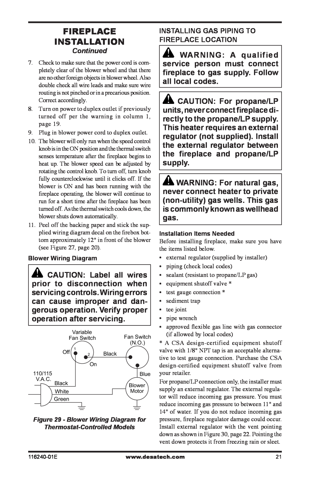
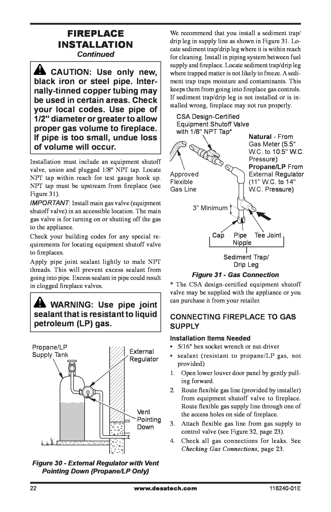
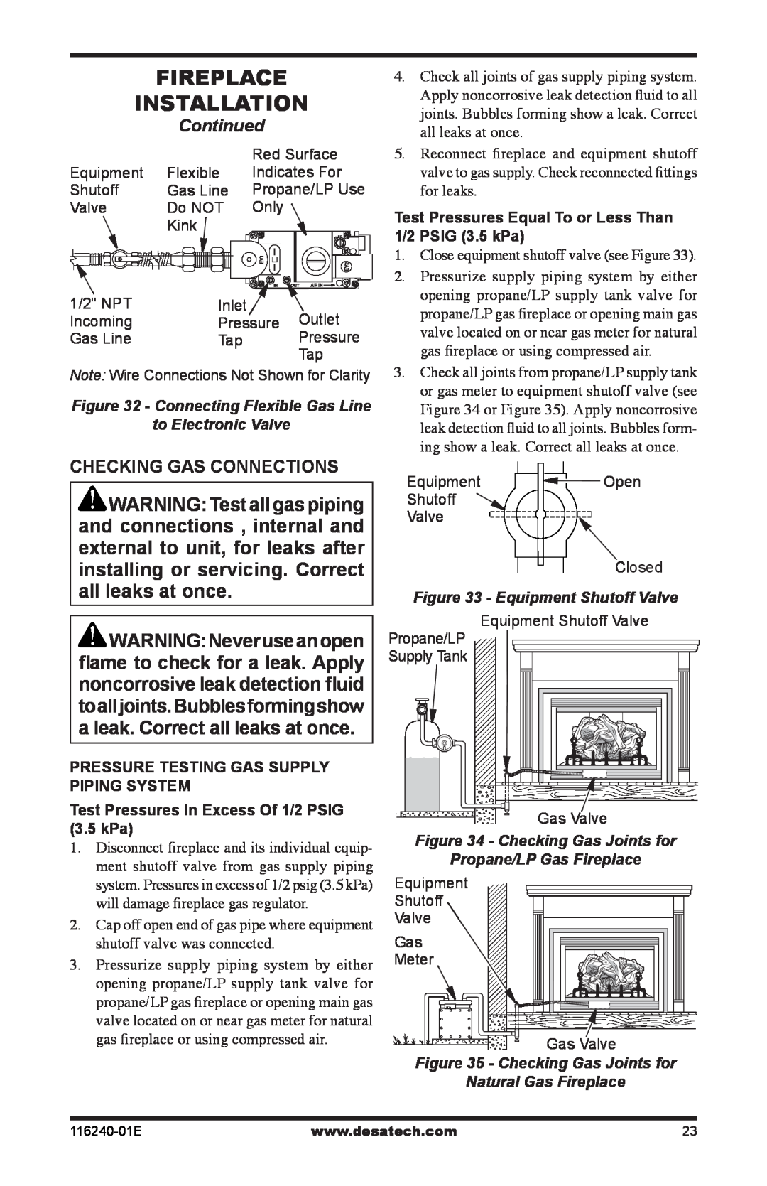
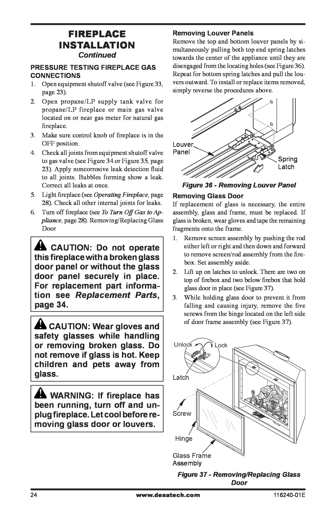
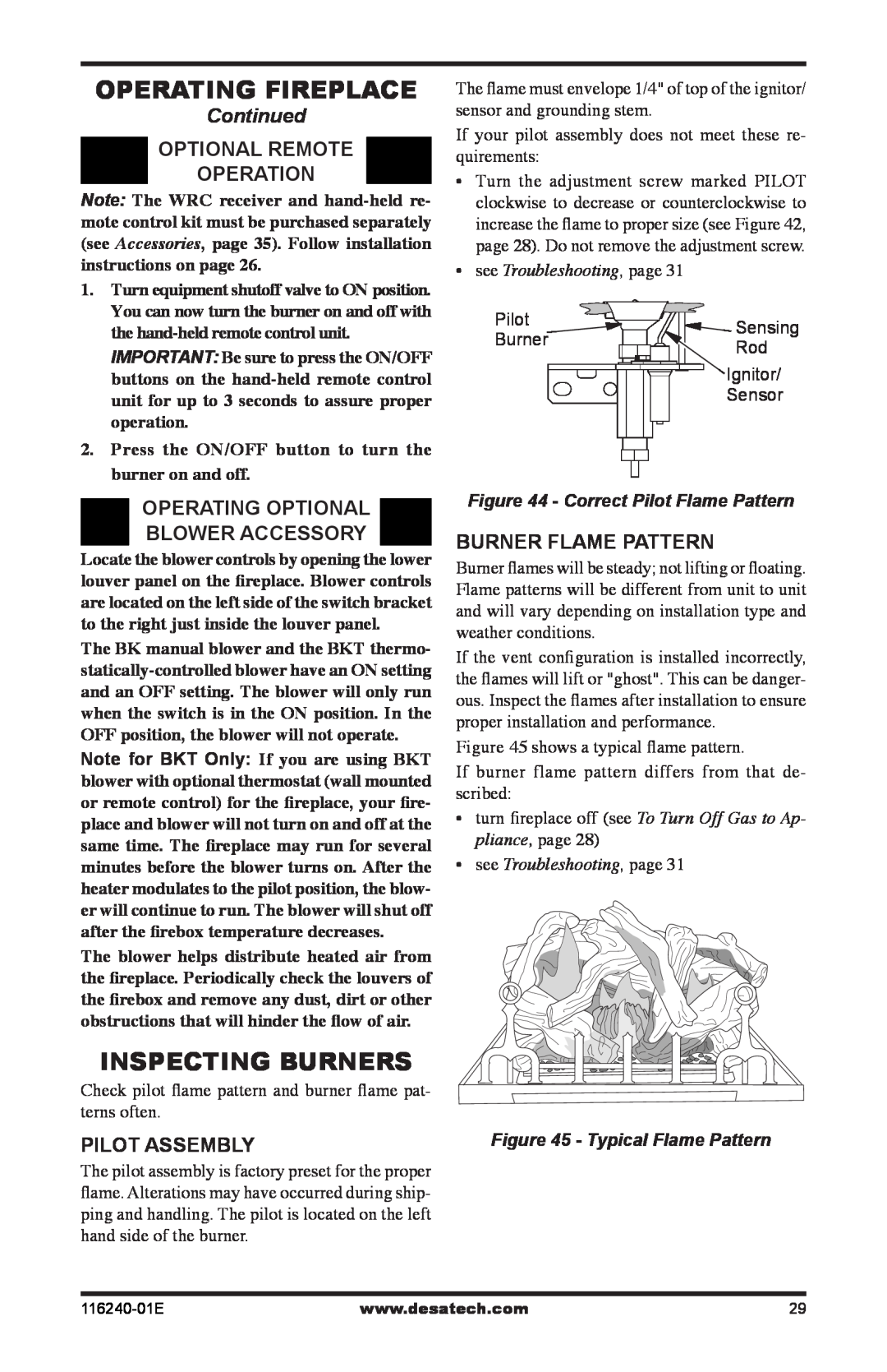
Image 16
Contents WHAT TO DO IF YOU SMELL GAS Table of Contents Safety InformationDANGER Carbon monoxide poisoning may lead to deathSafety information ContinuedSafety information ProductIdentification Local CodesProduct Features Pre-Installation PreparationFigure 3 - Fireplace Bottom Dimensions Location and space requirementsContinued ClearancesPre-Installation InstallationPreparation ContinuedD E B L Location of Termination CapFigure 7 - Minimum Clearances for Termination Cap Venting Installation Instructions Venting Installation instructions INSTALLATION PLANNINGContinued Figure 8 - Vent Pipe ConnectionsFigure 10 - Installing Horizontal Vent Cap Figure 11 - Installing Siding StandoffFigure 12 - Connecting Vent Cap with ContinuedGROUND FLOOR INSTALLATION ContinuedSquare Termination VerticalCORNER INSTALLATION SNORKEL TERMINATION INSTALLATIONContinued 90 ElbowHORIZONTAL SYSTEM INSTALLATION USING TWO 90 ELBOWSContinued with Termination at 90 with Fireplaceinstallation for vertical termination Flat Ceiling InstallationFigure 20 - Installing Firestop ContinuedConfiguration Using Two 90 Elbows Configuration Using One 90 ElbowContinued Figure 21 - Vertical VentingConfiguration Using Two 90 Elbows Configuration With No Horizontal RunContinued Vertical Ventingparts list for venting kits and components ContinuedDESA 5/8 Pipe & Vent Kits Number Description Number DescriptionInstalling optional blower accessories Fireplace InstallationCHECK GAS TYPE Continued Model BKT InstallationFigure 28 - Blower Model BKT Blower Wiring Diagram Installing Gas Piping to Fireplace LocationInstallation Items Needed Installation Items Needed ContinuedFigure 30 - External Regulator with Vent Pointing Down Propane/LP OnlyContinued CHECKING GAS CONNECTIONSPressure Testing Fireplace Gas Connections Removing Louver PanelsFigure 36 - Removing Louver Panel Removing Glass DoorInstalling lava rock and glowing embers Installing Lava Rock and Glowing Embers, page Figure 40 - Installing the WRC Remote ReceiverFigure 39 - Installing Rear Brick Panel Figure 41 - Installing Battery into Back ofIGNITOR LEAD PILOT24V AC 120V ACfor your safety Read before lighting Operating Fireplacelighting instructions TO TURN OFF GAS TO APPLIANCEsee Troubleshooting, page see Troubleshooting, pageContinued Figure 44 - Correct Pilot Flame PatternCleaning and Maintenance CAUTION Do not vacuum if pieces are hotCleaning and Maintenance TroubleshootingOBSERVED PROBLEM venting systemWiring Diagram, page TROUBLESHOOTINGContinued WARNING If you smell gas Shut off gas supply Replacement Parts Service HintsTechnical Service SpecificationsAccessories 7 8 24 22 23 4 1 9 11 3 14 16116240-01E PARTS LIST illustrated parts breakdown Burner Pan Assembly KEEP THIS WARRANTY Warranty InformationLIMITED WARRANTY DIRECT-VENTFIREPLACE