OPERATING FIREPLACE
Lighting Instructions (Cont.)
To Turn Off Gas To Appliance
Manual Lighting Procedure
Optional
17
OPERATING FIREPLACE
Continued
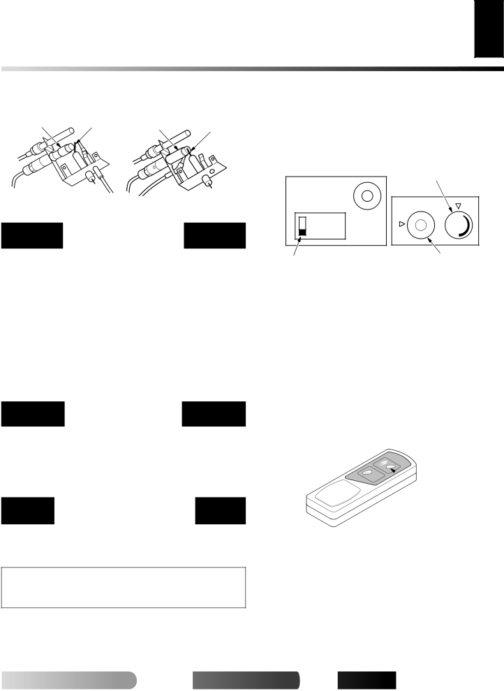
Pilot Burner | Ignitor |
| Ignitor | |
Electrode | Pilot Burner | |||
Electrode | ||||
|
|
|
Figure 33 - Pilot (Natural) | Figure 34 - Pilot (Propane/LP) |
TO TURN OFF GAS
TO APPLIANCE
Shutting Off Heater
1.Turn control knob clockwise ![]() to the OFF position.
to the OFF position.
2a. Set selector switch in the OFF position.
2b. If Using Optional
Shutting Off Burners Only (pilot stays lit)
You may shut off the burners and keep the pilot lit by doing one of the following:
•Turn control knob clockwise ![]() to the PILOT position.
to the PILOT position.
•Use remote control manual OFF button.
•Set selector switch in the OFF position.
MANUAL LIGHTING
PROCEDURE
1.Follow steps 1 through 6 under Lighting Instructions, page 16.
2.Depress control knob and light pilot with match.
3.Keep control knob pressed in for 30 seconds after lighting pilot. After 30 seconds, release control knob. Now follow steps 9 through 11, page 16.
OPTIONAL HAND-HELD
REMOTE OPERATION
Note: All remote control accessories must be purchased sepa- rately (see Accessories, pages 28 through 30 ). Follow instruc- tions included with the remote control.
NOTICE: You must light the pilot before using the
1.After lighting, let pilot flame burn for about one minute. Turn control knob to ON position. Adjust flame adjustment knob anywhere between HI and LO. Slide the selector switch to the REMOTE position (see Figure 35). Note: The burner may light if
was last turned off. You can now turn the burner on and off with the
IMPORTANT: Do not leave the selector switch in the RE- MOTE or ON position when the pilot is not lit. This will drain the battery.
| Flame Adjustment Knob | ||
ON |
|
| OL |
N |
|
| |
|
|
| |
OFF | O |
| O |
|
| ||
REMOTE | T | F | |
O |
| ||
F | HI | ||
| LI P |
| |
Selector Switch in Remote Position | Control Knob in | |
On Position | ||
(Optional | ||
|
Figure 35 - Setting the Selector Switch, Control Knob, and Flame Adjustment Knob for Hand-Held Remote Operation
ON/OFF SERIES
(MODELS GHRCB AND CGHRCB)
Hold the control button on the
TO LOCK press both buttons on
TO UNLOCK press both buttons together on
![]() Control Button
Control Button
Turns Burners
On and Off
Figure 36 - On/Off Hand-Held Remote Control Unit (C)GHRCB
THERMOSTAT SERIES
(MODELS GHRCTB AND CGHRCTB)
The
For more![]()
![]()
![]() visit www.
visit www.![]()
![]()
![]() .com
.com![]()
![]()
![]()
![]()