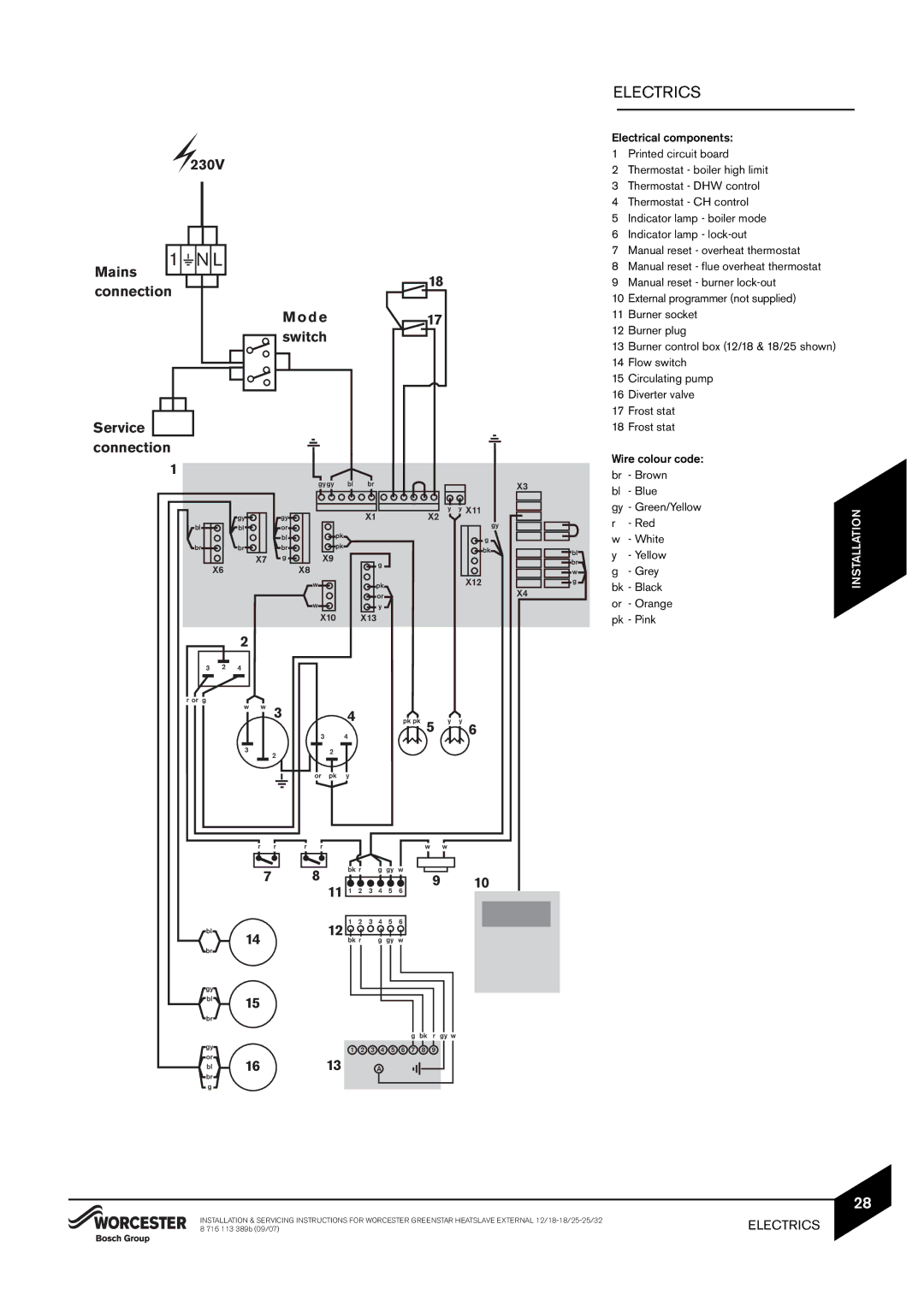
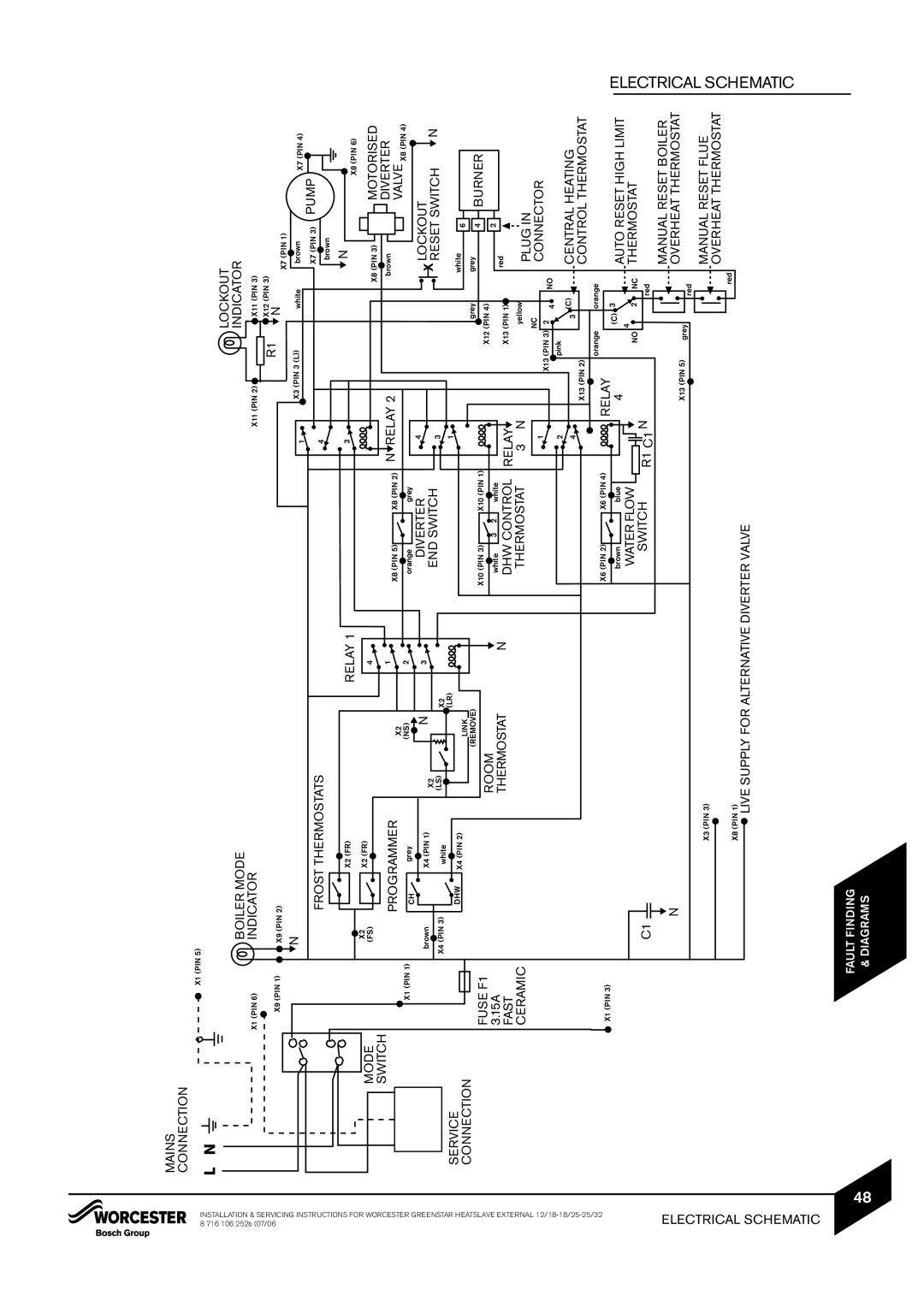
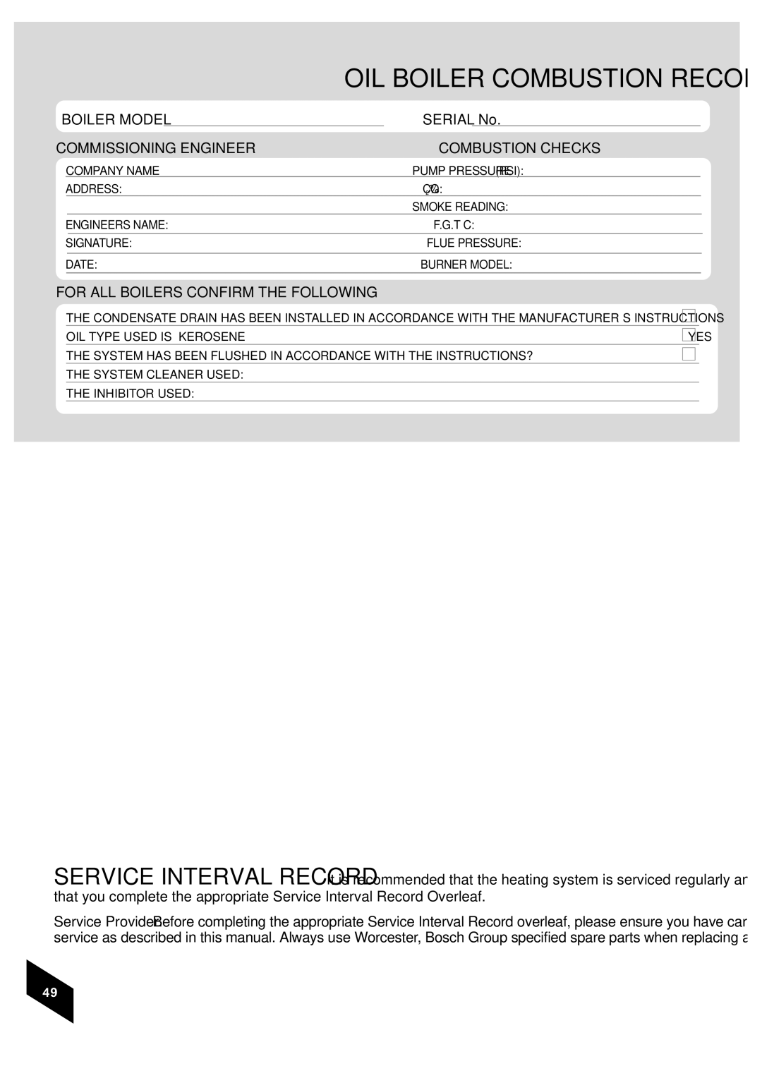
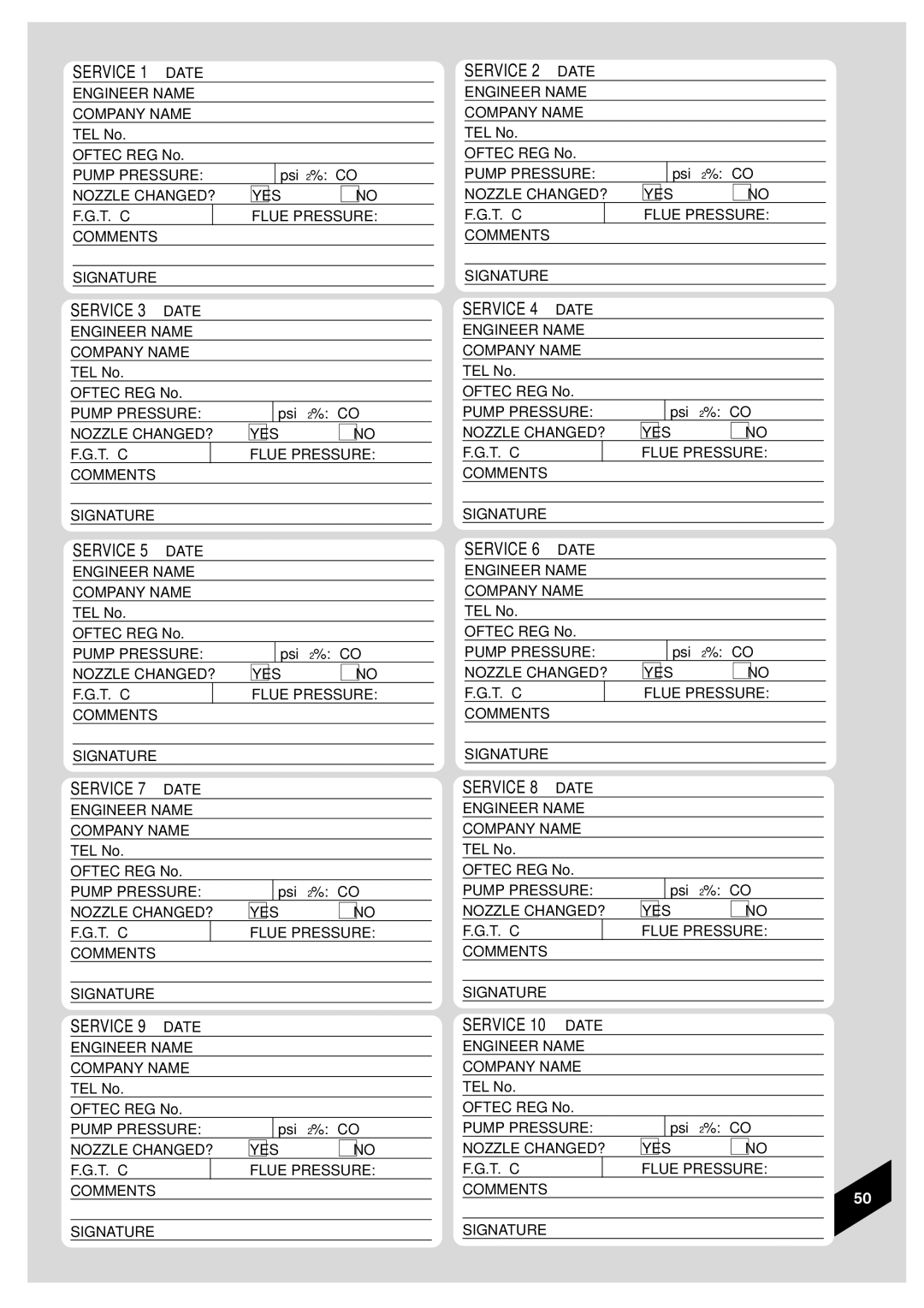
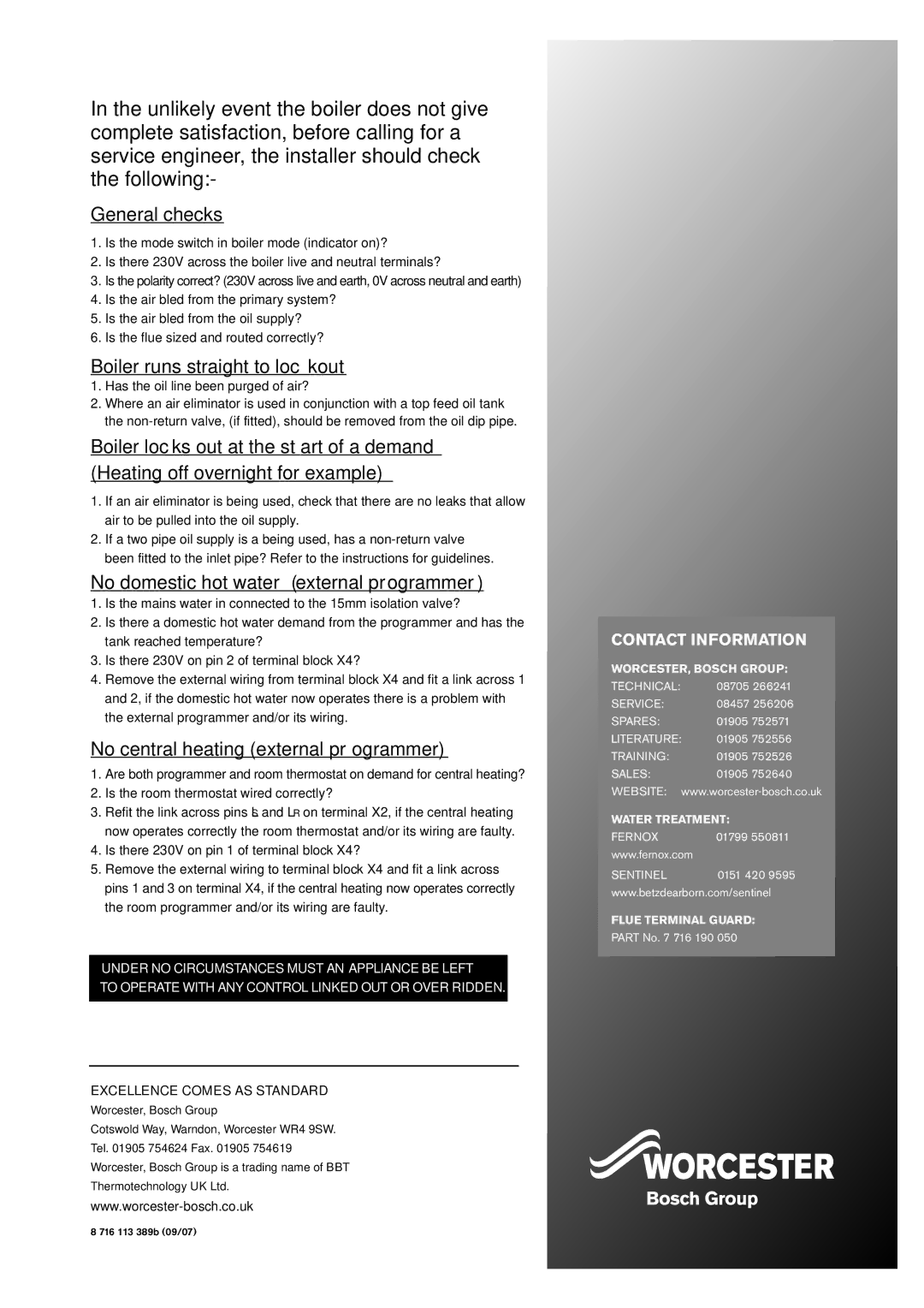
Bosch Appliances 25/32kW, 18/25, 12/18 instruction manual Electrical, Schematic

Page 49

INSTALLATION & SERVICING INSTRUCTIONS FOR WORCESTER GREENSTAR HEATSLAVE EXTERNAL 12/18-18/25-25/32 8 716 106 252b (07/06ELECTRICAL

MAINS


CONNECTION


L

X1 (PIN 5)


N


LOCKOUT


BOILER MODE


INDICATOR


X1 (PIN 6)

INDICATOR


X11 (PIN 2)

X11 (PIN 3)


R1

X12 (PIN 3)


X9 (PIN 1)

X9 (PIN 2)


N


X7 (PIN 1)


N


1

X3 (PIN 3 (L))

white

brown


X7 (PIN 4)


FROST THERMOSTATS


4


X7 (PIN 3)

PUMP


brown


X2 (FR)


RELAY 1


3


N


X8 (PIN 6)


X2


MODE

X2 (FR)


4


MOTORISED


(FS)


X8 (PIN 3)


SWITCH

PROGRAMMER


1

X8 (PIN 5)


X8 (PIN 2)

N RELAY 2


brown


DIVERTER


X2


VALVE X8 (PIN 4)


2


X1 (PIN 1)

CH

grey

(NS)

orange


grey


N


DIVERTER


4


LOCKOUT


brown

X4 (PIN 1)

3


X2


END SWITCH


3


RESET SWITCH

N


X4 (PIN 3)

white

(LS)

X2


1


SERVICE

DHW

X4 (PIN 2)


(LR)


white


6


CONNECTION


LINK


grey


grey


FUSE F1


(REMOVE)


X10 (PIN 3)


X10 (PIN 1)


4

BURNER


ROOM


X12 (PIN 4)


3.15A


white

3

2

white


2


THERMOSTAT

N


red


FAST


DHW CONTROL

RELAY

X13 (PIN 1)


CERAMIC


THERMOSTAT

3

N


yellow


PLUG IN


NC


1


CONNECTOR


X13 (PIN 3)

2

NO


2

pink

4


3 (C)


CENTRAL HEATING


4


X13 (PIN 2)


CONTROL THERMOSTAT


X6 (PIN 2)


X6 (PIN 4)


orange

orange


X1 (PIN 3)


RELAY

(C) 3


brown


blue


4


AUTO RESET HIGH LIMIT


4


WATER FLOW


THERMOSTAT


R1 C1 N

NO

2

NC


C1


SWITCH


red


N


MANUAL RESET BOILER


OVERHEAT THERMOSTAT


X13 (PIN 5)

grey


red


X3 (PIN 3)


MANUAL RESET FLUE


OVERHEAT THERMOSTAT


ELECTRICAL

X8 (PIN 1)

red

SCHEMATIC

48

LIVE SUPPLY FOR ALTERNATIVE DIVERTER VALVE

FAULT FINDING

& DIAGRAMS

SCHEMATIC

Image 49
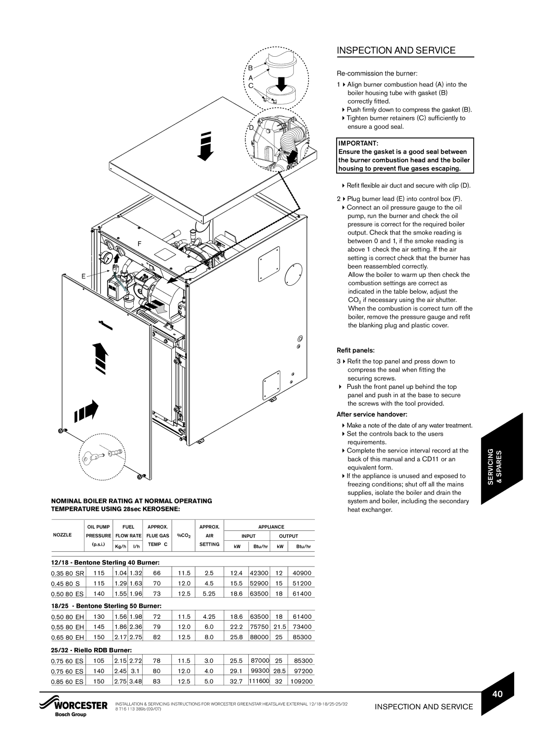
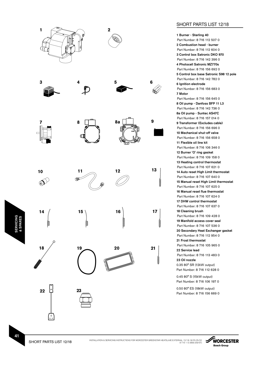
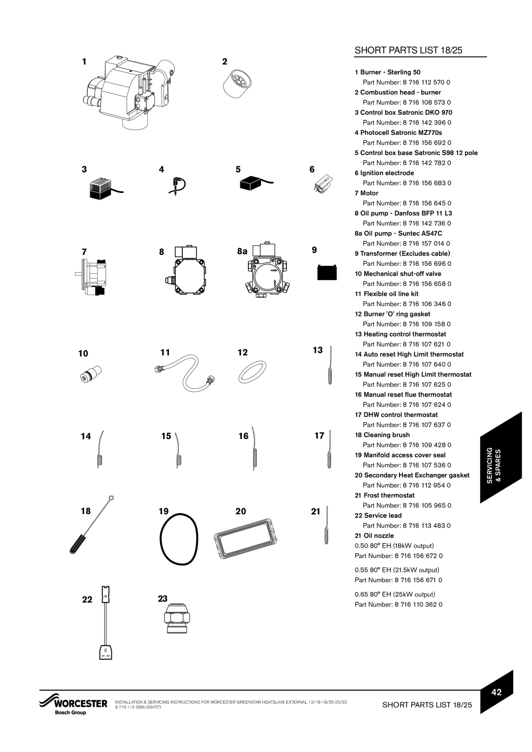
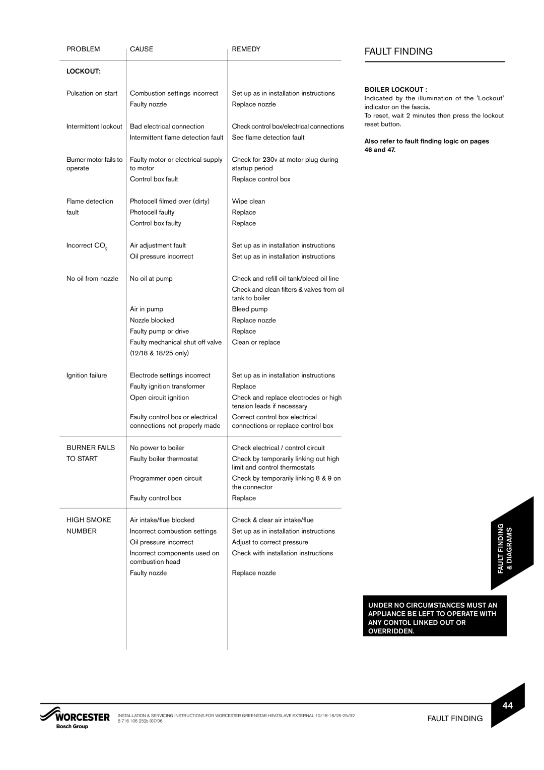
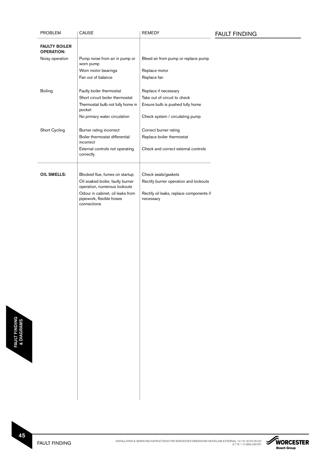
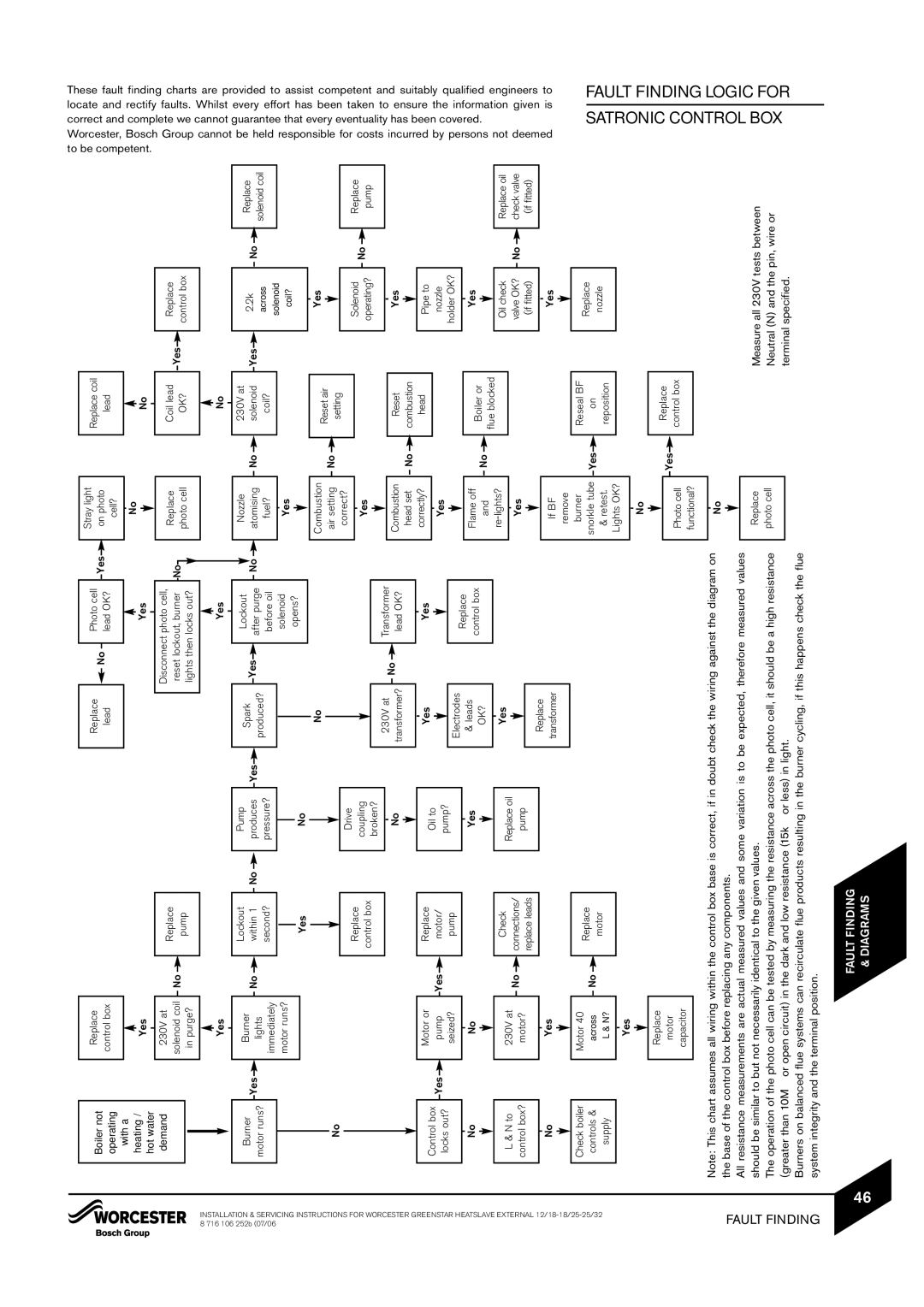
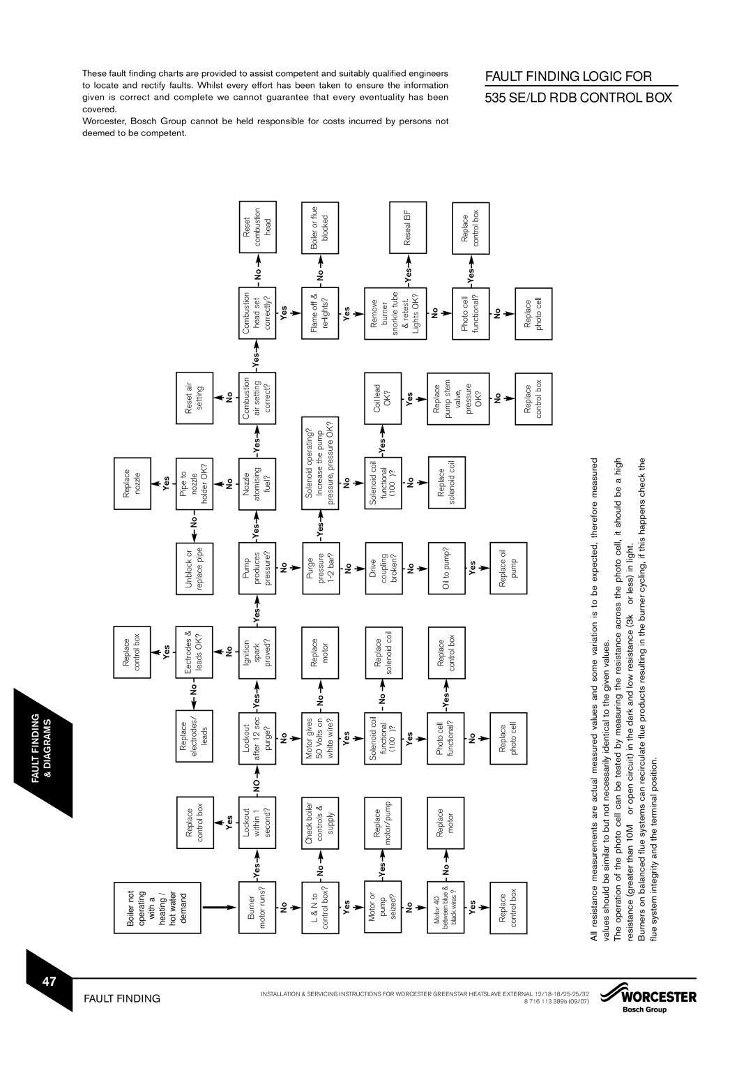
Contents Greenstar Heatslave External 12/18, 18/25, 25/32kW Installation & Servicing Instructions Installation & Servicing InstructionsContents Installation Regulations Safety PrecautionsSafety Precautions Installation Regulations OIL SMELLS, Leaks or Fumes from the ApplianceGeneral Information General InformationStandard Package Technical Data Technical DataDescription BSPLayout & Components Layout & ComponentsCleaning Primary Systems Cleaning Primary SystemsMains Supplies Mains SuppliesMains Water Expansion Vessel Electric SupplyOIL Supply OIL SupplyG J HeadWater Systems & Pipework Water Systems & PipeworkSHOWERS/BIDETS Filling Primary Sealed SystemsDomestic HOT Water Condensate Pressure Relief Pipework Condensate Pressure Relief PipeworkCondensate Pipework Pressure Relief PipeworkBoiler Location Boiler Location ClearancesClearances FrontCabinet Mounted LOW Level Flue Terminal Positions Cabinet Mounted LOW Level Flue Terminal PositionsTerminal Position Positions High Level Flue TerminalHigh Level Flue Terminal PositionsBalanced External Oilfit Balanced External Oilfit Flue OptionsFlue Options AC DHorizontal Flue Options Cabinet Mounted BalancedBalanced Flue Options Unpacking the Boiler Lifting and Carrying PrecautionsUnpacking the Boiler Pipework & Flue Positions SafetyPipework & Flue Positions Boiler Installation Boiler InstallationFlue Installation Flue InstallationInstallation Notes Combustion Chamber Combustion ChamberHor Plan sectional view Hook the retainer J over the end two bafflesPipework Connections Pipework ConnectionsWater Connections OIL Supply ConnectionsPressure Relief Connection Condensate ConnectionOIL Burner & Pump OIL Burner & PumpOIL Burner OIL PumpRefitting Components Refitting ComponentsPlug burner lead E into control box F Programmer External Electrics MainsBoard ElectricsBlue Green/Yellow Br BrownRed WhitePRE-COMMISSIONING PRE-COMMISSIONING Checks ApplianceChecks Appliance Filling the System Filling the SystemStarting the Appliance Starting the ApplianceSafely dispose of the container/discharge Boiler lockout indicator on Pressure adjustment Vacuum gauge port 25/32Bleed & pressure gauge port Holder with oilBurner should be OFF and the circulating pump on Set the room thermostat to minimum Central heating Open all radiator valvesWater Treatment Water TreatmentPump and all radiators Finishing Commissioning Finishing CommissioningAppliance Inspection and Service Inspection and ServiceRoutine servicing Loosen clip D to detach air duct3.0mm Clean both sides of the fan impeller Clean the BurnerThoroughly clean any deposits Any debris and clean if necessaryFront 11.5 18.6 50 80EH55 80EH 12.0 22.2Short Parts List 12/18 Short Parts List 12/18Auto reset High Limit thermostat Part Number 8 716 107 640 Burner SterlingShort Parts List 18/25 Short Parts List 18/25Manifold access cover seal Short Parts List 25/32 Short Parts List 25/32Fault Finding Fault Finding Faulty Boiler Operation Problem Cause Remedy Noisy operation Pump noise from air in pump or OIL SmellsBase of the control box before replacing any components Neutral N and the pin, wire orMeasure all 230V tests between Control BOX Logic for 535 SE/LD RDB Fault FindingElectrical SchematicOIL Boiler Combustion Record Service 1 Date Excellence Comes AS Standard General checks