SX), D4504S*F(BN, D4403S*F(BN specifications
Bradford-White Corp has long been a pioneering name in the water heating industry, and their D4403S*F(BN, D4504S*F(BN, and SX models represent the company’s commitment to delivering high-quality, efficient solutions for residential and commercial applications. These water heaters are designed with various user needs in mind, ensuring that homeowners and businesses can enjoy a reliable hot water supply whenever needed.One of the core features of these models is their advanced water heating technology. Utilizing power venting systems, these units ensure efficient heat transfer while minimizing heat loss. This technology promotes energy efficiency and helps users save on their energy bills. The power vent system also allows for flexible installation options, accommodating different types of venting configurations, which is especially useful in homes with unique designs or limited space.
The Bradford-White D4403S*F(BN and D4504S*F(BN models are equipped with their state-of-the-art Hydrojet Total Performance System. This feature not only enhances the heater's overall performance but also reduces sediment buildup within the tank, which can significantly extend the unit's lifespan and maintain efficiency over time. Moreover, the patented Vitraglas® lining protects the inner tank from corrosion, further prolonging the life of the appliance.
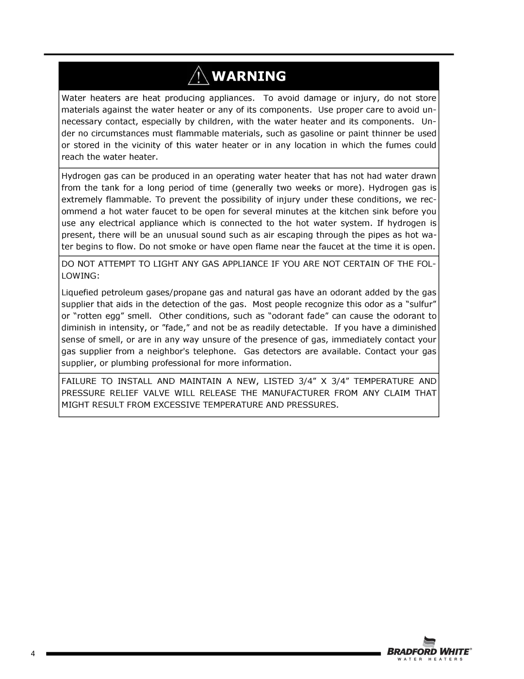
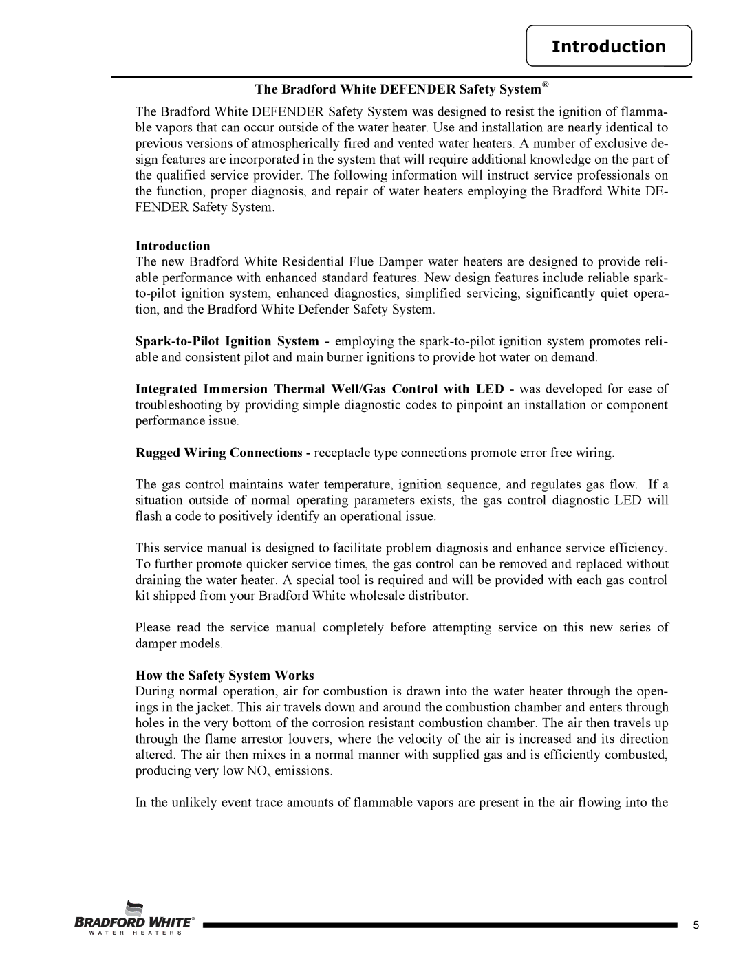
Safety is a paramount consideration in Bradford-White's design philosophy. Each model includes a robust Flammable Vapor Ignition Resistance (FVIR) system, which helps prevent the ignition of flammable vapors that may be present in the vicinity of the water heater. This feature meets stringent safety standards and provides peace of mind to users.
In terms of energy specifications, both the D4403S*F(BN and D4504S*F(BN models are designed to meet or exceed efficiency standards, contributing to lower energy consumption and environmental impact. The SX model is particularly notable for its user-friendly digital display and controls, allowing for easy temperature adjustments and efficient operation monitoring.
In conclusion, Bradford-White Corp's D4403S*F(BN, D4504S*F(BN, and SX models are a testament to the company’s dedication to quality, safety, and efficiency in water heating technology. With their innovative features, user-friendly design, and long-lasting durability, these water heaters are well-suited to meet the ever-evolving demands of modern households and commercial settings alike. As homeowners and businesses continue seeking reliable hot water solutions, Bradford-White stands out as a trusted choice in the industry.
