Westinghouse ETL-ES-Harmony-WH11 manual nOrMal dOwnrOd OPtiOn, PROCEED TO PAGE 11, STEP

Page 9
nOrMal dOwnrOd OPtiOn

ETL-ES-Harmony-WH11

nOrMal dOwnrOd OPtiOn

OPCión COn Varilla VertiCal Para CielOrrasO nOrMal

7

OPCión COn Varilla VertiCal Para CielOrrasO nOrMal 1

PROCEED TO PAGE 11, STEP 11. 2

CONTINÚE CON LA PÁGINA 11, PASO 11.Manual background 2

3

4

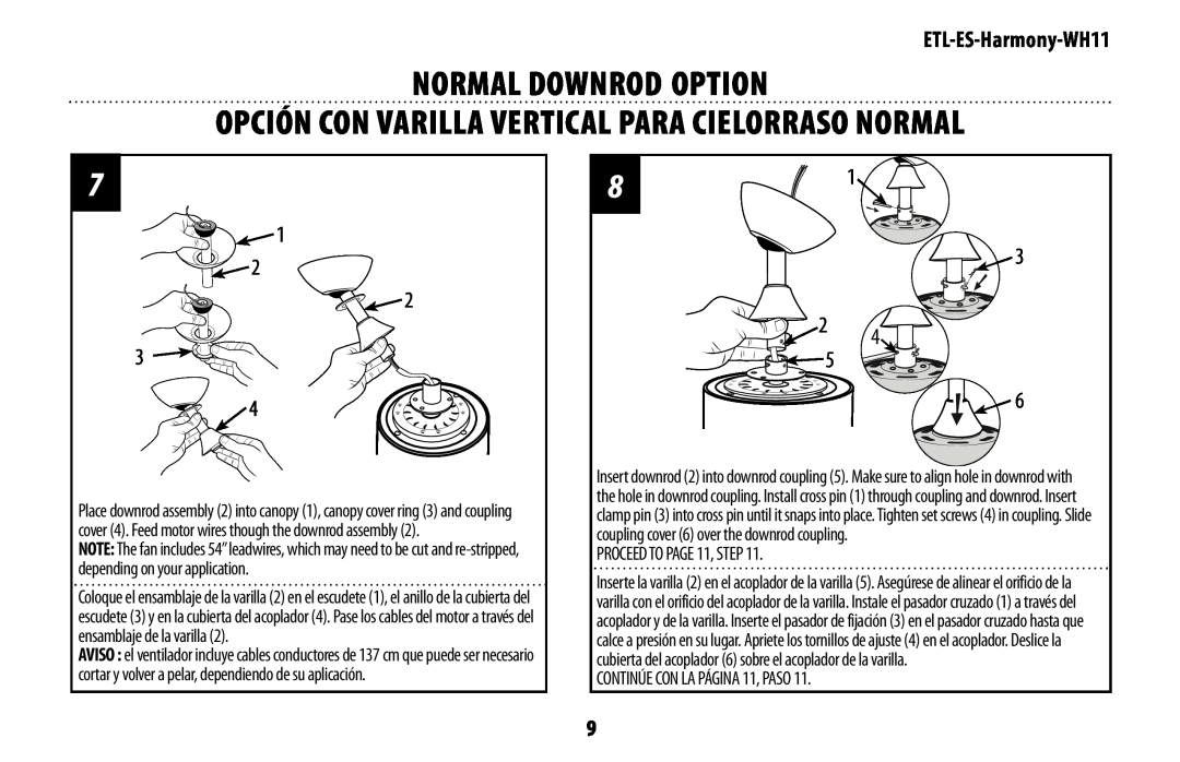
Place downrod assembly (2) into canopy (1), canopy cover ring (3) and coupling cover (4). Feed motor wires though the downrod assembly (2).

NOTE: The fan includes 54” leadwires, which may need to be cut and re-stripped, depending on your application.

Coloque el ensamblaje de la varilla (2) en el escudete (1), el anillo de la cubierta del escudete (3) y en la cubierta del acoplador (4). Pase los cables del motor a través del ensamblaje de la varilla (2).

AVISO : el ventilador incluye cables conductores de 137 cm que puede ser necesario cortar y volver a pelar, dependiendo de su aplicación.

81


3

2

4

5


6

Insert downrod (2) into downrod coupling (5). Make sure to align hole in downrod with the hole in downrod coupling. Install cross pin (1) through coupling and downrod. Insert clamp pin (3) into cross pin until it snaps into place. Tighten set screws (4) in coupling. Slide coupling cover (6) over the downrod coupling.

PROCEED TO PAGE 11, STEP 11.

Inserte la varilla (2) en el acoplador de la varilla (5). Asegúrese de alinear el orificio de la varilla con el orificio del acoplador de la varilla. Instale el pasador cruzado (1) a través del acoplador y de la varilla. Inserte el pasador de fijación (3) en el pasador cruzado hasta que calce a presión en su lugar. Apriete los tornillos de ajuste (4) en el acoplador. Deslice la cubierta del acoplador (6) sobre el acoplador de la varilla.

CONTINÚE CON LA PÁGINA 11, PASO 11.

9
Image 9
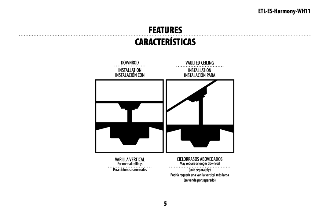
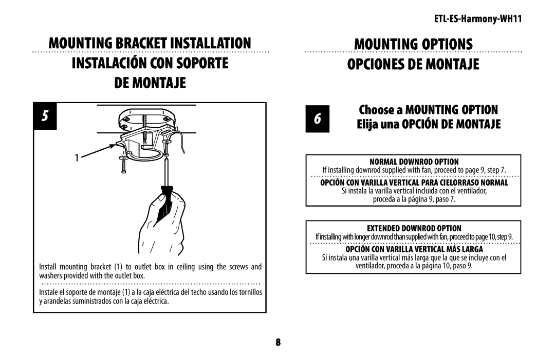
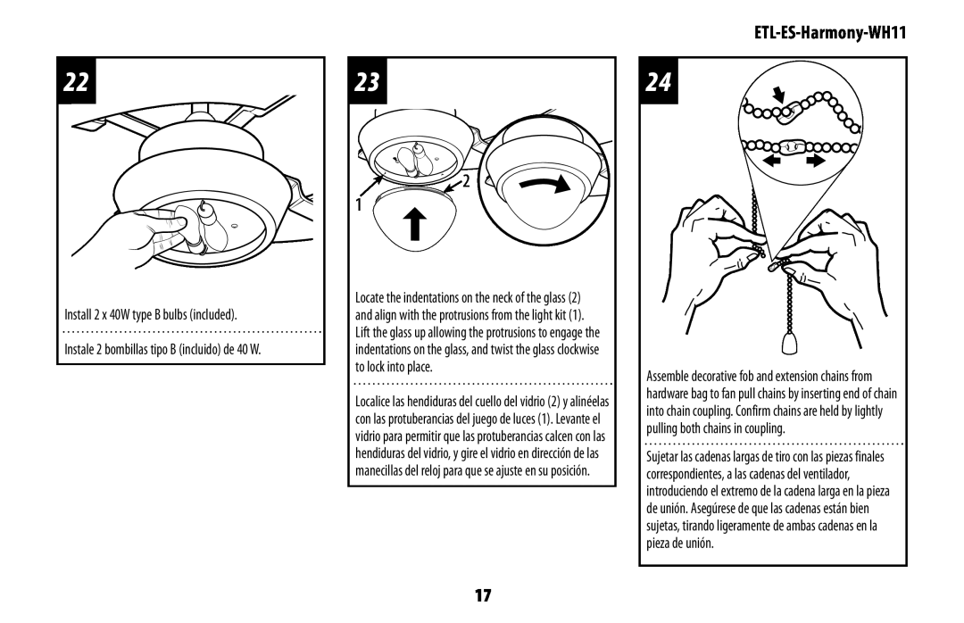
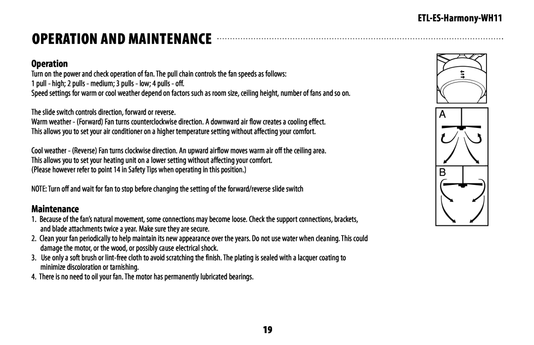
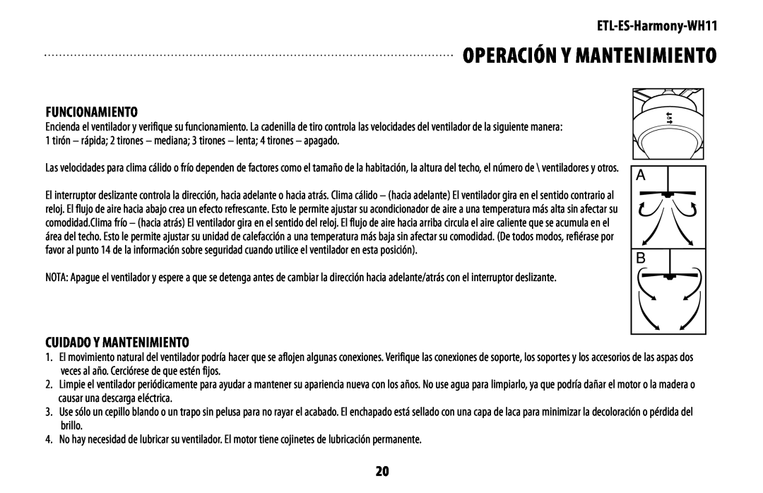
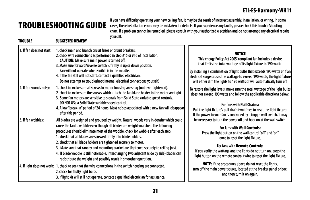
Contents 15.4 net weightETL-ES-Harmony-WH11 Peso netoETL-ES-Harmony-WH11 wire Cutters safety tiPsETL-ES-Harmony-WH11 PliersPinzas COnsejOs de seGuridadescalera de mano Pinzas de corteFor normal ceilings features CaraCterístiCasMay require a longer downrod sold separatelyPreParinG fOr installatiOn antes de la instalaCión Suelte los tornillos de ajuste 1 en el acoplador Loosen the set screws 1 on the couplingMOuntinG OPtiOns OPCiOnes de MOntaje MOuntinG BraCKet installatiOn instalaCión COn sOPOrte de MOntajeChoose a MOuntinG OPtiOn elija una OPCión de MOntajeOPCión COn Varilla VertiCal Para CielOrrasO nOrMal nOrMal dOwnrOd OPtiOnPROCEED TO PAGE 11, STEP CONTINÚE CON LA PÁGINA 11, PASOeXtended dOwnrOd OPtiOn OPCión COn Varilla VertiCal MÁs larGa Repeat this step for remaining blade assembly Blade installatiOn instalaCión de las PaletasRepeat this step for remaining blade Repita este paso para el aspa restanteMOuntinG MOntaje wall COntrOl wirinG OPtiOn wirinG OPtiOns OPCión de CaBleadOPull CHain wirinG OPtiOn OPCión de CaBleadO Para Cadenilla de tirOseCure tO CeilinG aseGure el VentiladOr al CielOrrasO liGHt fiXture installatiOn instalaCión del artefaCtO luMinOsO 3. Push the connections neatly into the mounting ring Instale 2 bombillas tipo B incluido de 40 W Install 2 x 40W type B bulbs includedETL-ES-Harmony-WH11 OPeratiOn and MaintenanCe MaintenanceOperation FUNCIONAMIENTO CUIDADO Y MANTENIMIENTOOPeraCión y ManteniMientO For fans with Remote Controls trOuBlesHOOtinG GuideTROUBLE SUGGESTED REMEDYPROBLEMA Guía Para sOluCiOnar PrOBleMas3. NO USE un control de velocidad variable de estado sólido 2. compruebe si hay lámparas defectuosasETL-ES-Harmony-WH11 titular de la licencia de Westinghouse Electric Corporation