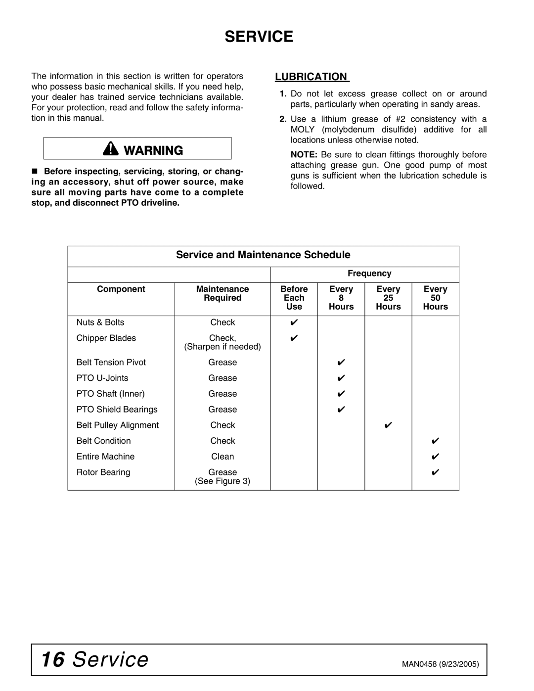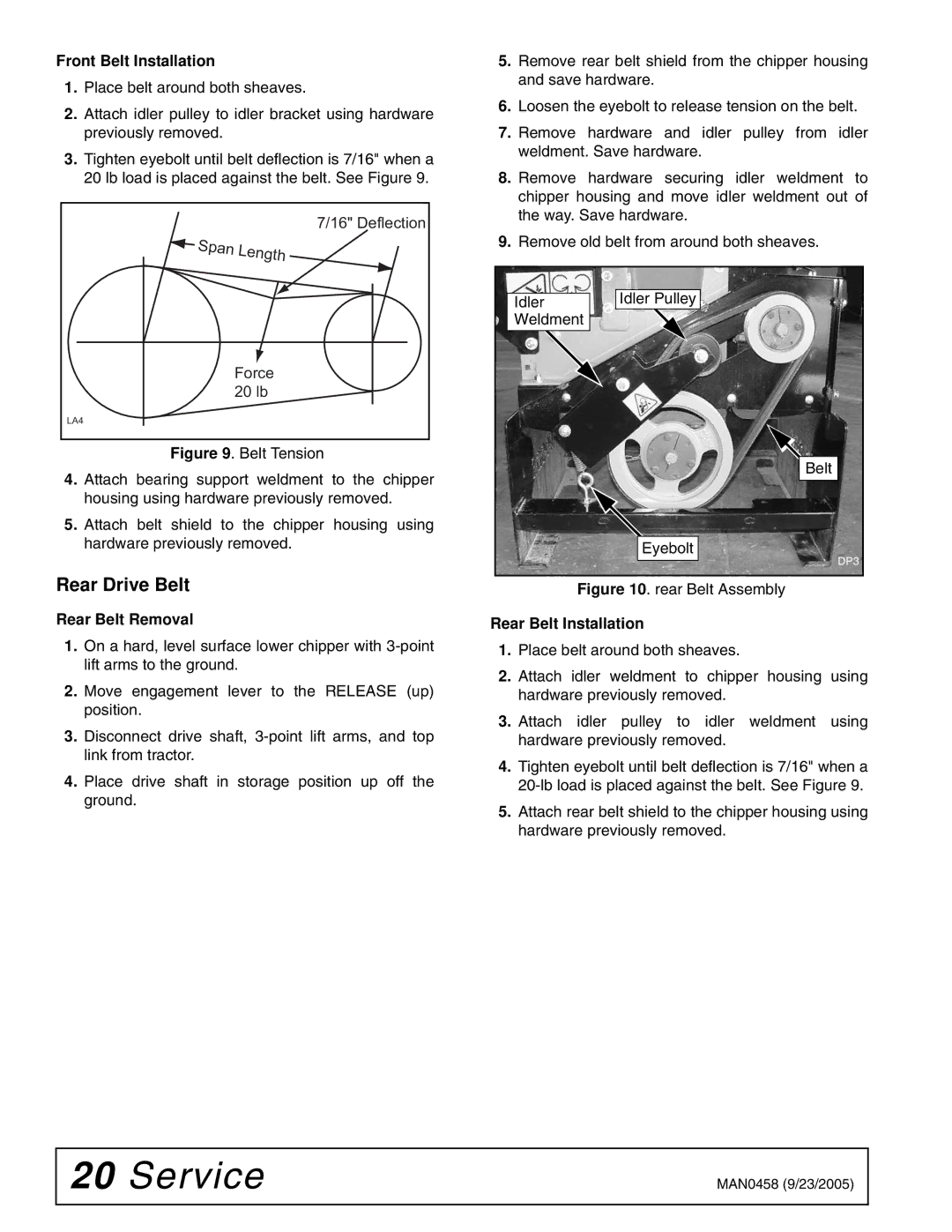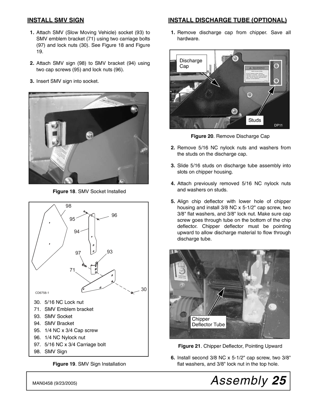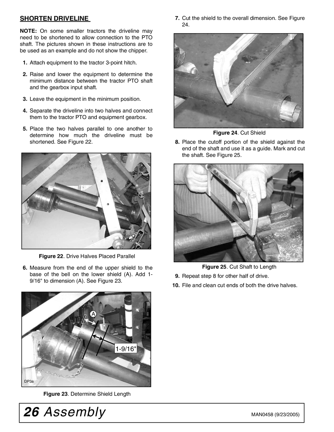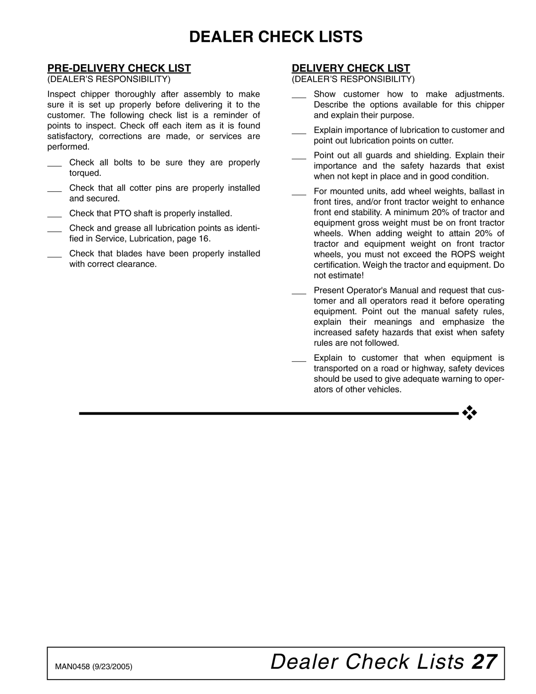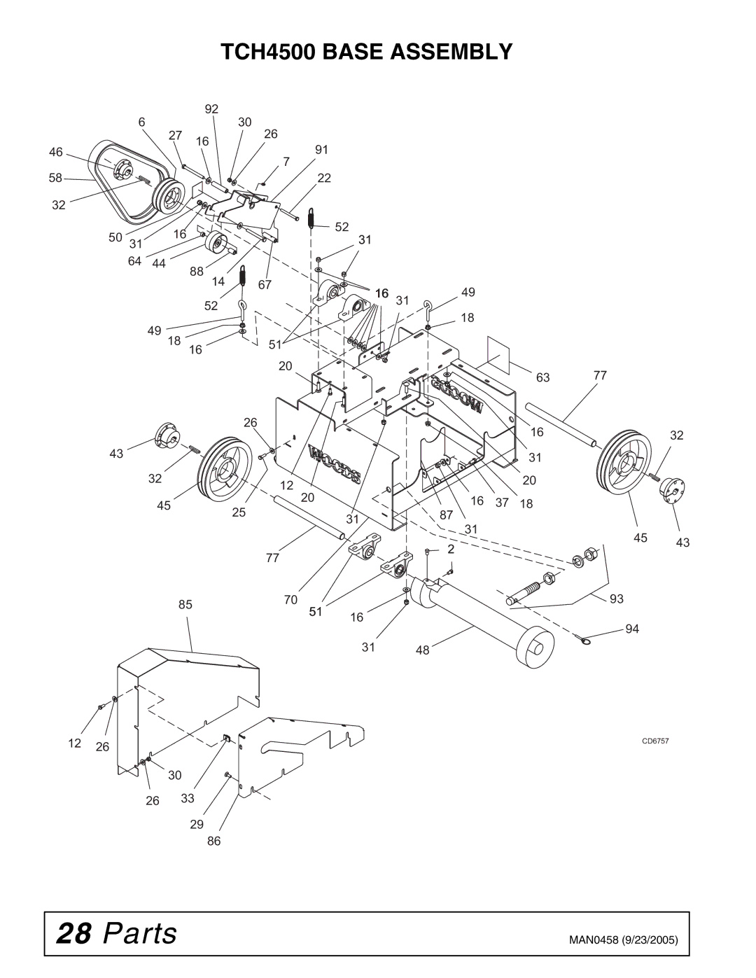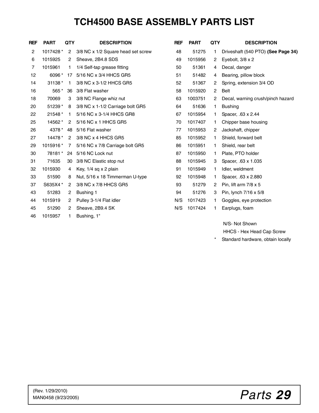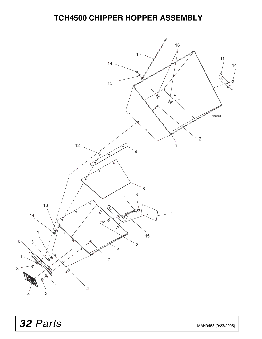
3.Attach locking plate (15) to the opposite side of the chipper hopper using two carriage bolts (2), flat
washers (1), and stop nuts (3).
13
16
14
|
|
| DP7 |
| Hinge |
|
|
|
|
|
|
|
|
| |
|
|
|
|
|
|
| |
|
|
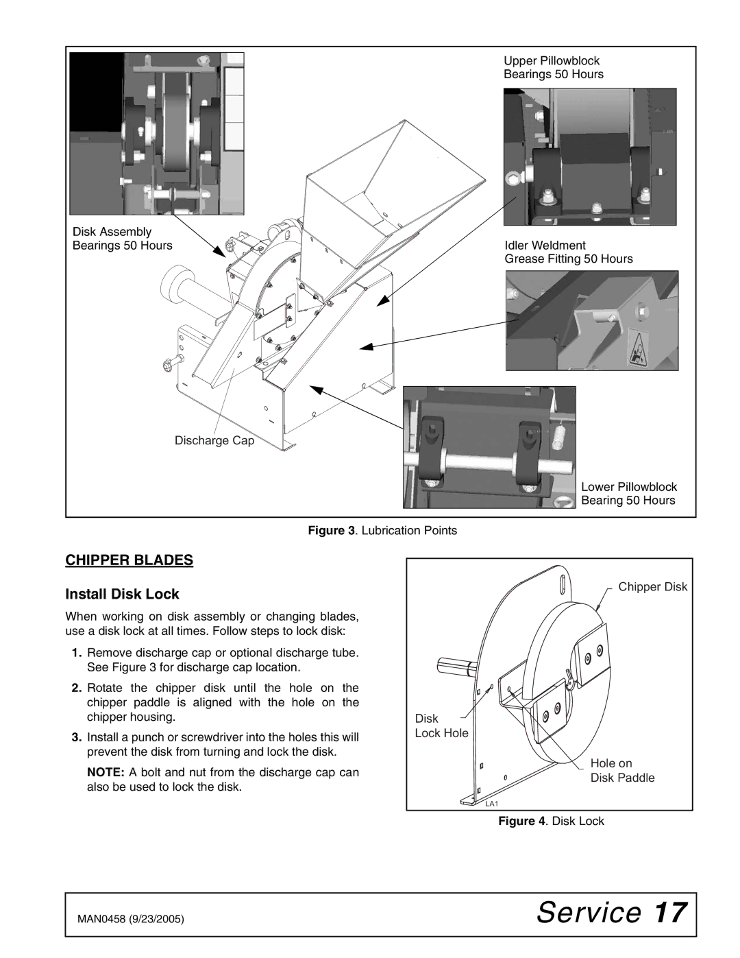
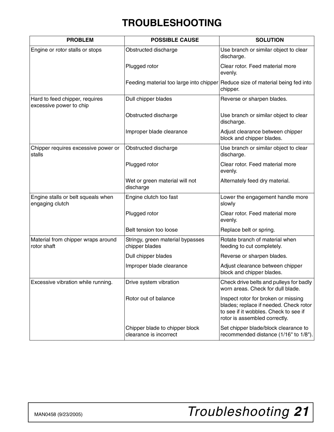
| Figure 15. Lanyard Installed |
|
|
| |
3 |
|
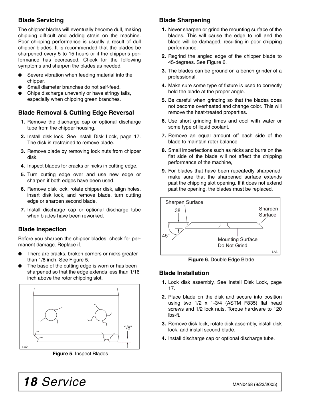
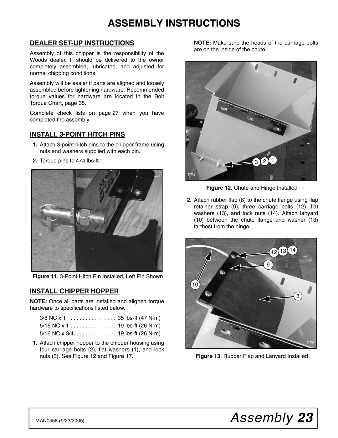
| 6. Attach latch (11) to chute extension using two | ||||
| 2 |
| |||||
|
| carriage bolts (16) and lock nuts (14). |
|
|
| ||
15 | 1 |
|
|
|
| ||
|
|
|
|
|
| ||
|
|
|
|
|
|
| |
DP6 |
|
|
|
|
|
|
|
|
| 16 |
|
|
|
| |
|
|
|
|
|
|
| |
Figure 14. Locking Plate Installed |
|
|
|
|
|
| |
|
| 14 |
|
|
|
| |
4. Place chute extension (7) on chipper hopper and | 11 |
|
|
| |||
|
|
|
| ||||
|
|
|
|
| |||
attach it to hinge (6) using three carriage bolts (2), |
|
|
|
|
| ||
flat washers (1), and stop nuts (3). |
|
|
|
|
|
|
|
5.Attach lanyard (10) to chute extension (7) using carriage bolt (16), flat washer (13), and lock nut (14).
|
|
|
|
|
|
| DP8 |
|
|
|
|
|
|
|
| Figure 16. Hinge Latch Installed | |
|
|
|
| 16 |
|
|
|
|
|
|
|
| 10 |
| 11 14 |
|
|
|
|
|
| 14 |
| 1. | 3/8 Flat washer | |
|
|
|
|
|
|
| ||
|
|
|
| 13 |
|
| 2. | 3/8 NC x 1 Carriage bolt GR5 |
|
|
|
|
|
|
| 3. | 3/8 NC Elastic stop nut |
|
|
| 12 | 9 |
|
| 5. | Chipper hopper |
|
|
|
| 6. | Hinge | |||
|
|
|
|
| ||||
|
|
|
|
|
|
| ||
|
|
|
| 8 | 2 |
| 7. | Chipper extension |
|
|
|
|
| 8. | Rubber flap | ||
|
|
|
| 7 |
|
| ||
| 13 |
| 1 | 3 |
|
| 9. | Flap retainer strap |
|
|
|
|
|
| 10. | Lanyard, 20” | |
14 |
|
|
|
|
| |||
|
|
|
|
| 11. | Latch | ||
| 1 |
|
|
|
|
| ||
6 |
|
| 2 15 |
|
| 12. | 5/16 NC x 1 Carriage bolt GR5 | |
3 |
|
|
|
| ||||
|
|
|
| 13. | 5/16 Flat washer | |||
1 |
|
|
| 5 |
|
| ||
|
| 2 |
|
| 14. | 5/16 NC Lock nut | ||
|
|
|
|
| ||||
3 |
| 1 | 2 |
|
|
| 15. | Locking plate |
|
|
|
| 16. | 5/16 NC x 3/4 Carriage bolt GR5 | |||
|
|
|
|
|
| |||
|
|
|
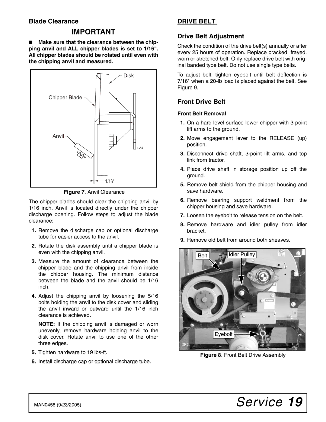
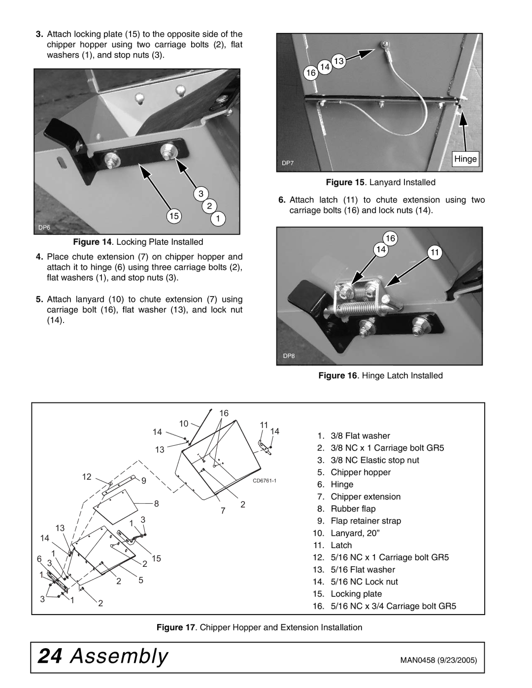
| Figure 17. Chipper Hopper and Extension Installation | ||||
24 Assembly | MAN0458 (9/23/2005) |
|
|
