DeviceNet Network Scanner DVPDNET-SL
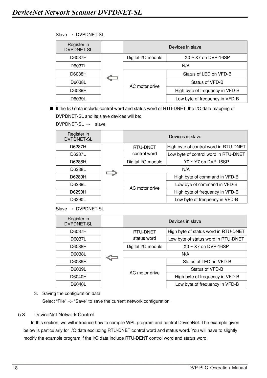
Slave →
Register in |
|
| Devices in slave |
|
|
| |
|
|
| |
D6037H |
| Digital I/O module | X0 ~ X7 on |
|
|
|
|
D6037L |
|
| N/A |
|
|
|
|
D6038H |
|
| Status of LED on |
|
|
|
|
D6038L |
| AC motor drive | Status of |
|
|
| |
D6039H |
| High byte of frequency in | |
|
| ||
|
|
| Low byte of frequency in |
D6039L |
|
| |
|
|
|
|
If the I/O data include control word and status word of
Register in |
|
| Devices in slave |
|
|
|
|
| |
|
|
|
| |
D6287H |
|
| High byte of control word in |
|
D6287L |
| control word | Low byte of control word in |
|
|
|
|
|
|
D6288H |
| Digital I/O module | Y0 ~ Y7 on |
|
|
|
|
|
|
D6288L |
|
| N/A |
|
|
|
|
|
|
D6289H |
|
| High byte of command in |
|
D6289L |
| AC motor drive | Low bye of command in |
|
|
|
|
| |
D6290H |
| High byte of frequency in |
| |
|
|
| ||
|
|
|
|
|
D6290L |
|
| Low byte of frequency in |
|
|
|
|
|
|
Slave → |
|
|
| |
|
|
|
| |
Register in |
|
| Devices in slave |
|
|
|
|
| |
|
|
|
| |
D6037H |
|
| High byte of status word in |
|
D6037L |
| status word | Low byte of status word in |
|
|
|
|
|
|
D6038H |
| Digital I/O module | X0 ~ X7 on |
|
|
|
|
|
|
D6038L |
|
| N/A |
|
|
|
|
|
|
D6039H |
|
| Status of LED on |
|
|
|
|
|
|
D6039L |
| AC motor drive | Status of |
|
D6040H |
| High byte of frequency in |
| |
|
|
| ||
|
|
| Low byte of frequency in |
|
D6040L |
|
|
| |
|
|
|
|
|
3.Saving the configuration data
Select “File” => “Save” to save the current network configuration.
5.3DeviceNet Network Control
In this section, we will introduce how to compile WPL program and control DeviceNet. The example given below is particularly for I/O data excluding
18 |