DeviceNet Network Scanner
DVPDNET-SL.
zWhen
zUse slotted screwdriver to adjust the DIP switch carefully in case you scratch the switch.
2.6Digital Indicator
The digital indicator provides the following two functions:
DVPDNET
POWER
MS
NS
1.Displaying the node address and error messages of
2.Displaying the error message of slave.
2.7I/O Module Connection Port
The I/O module connection port is used on connecting
3Basic Operation
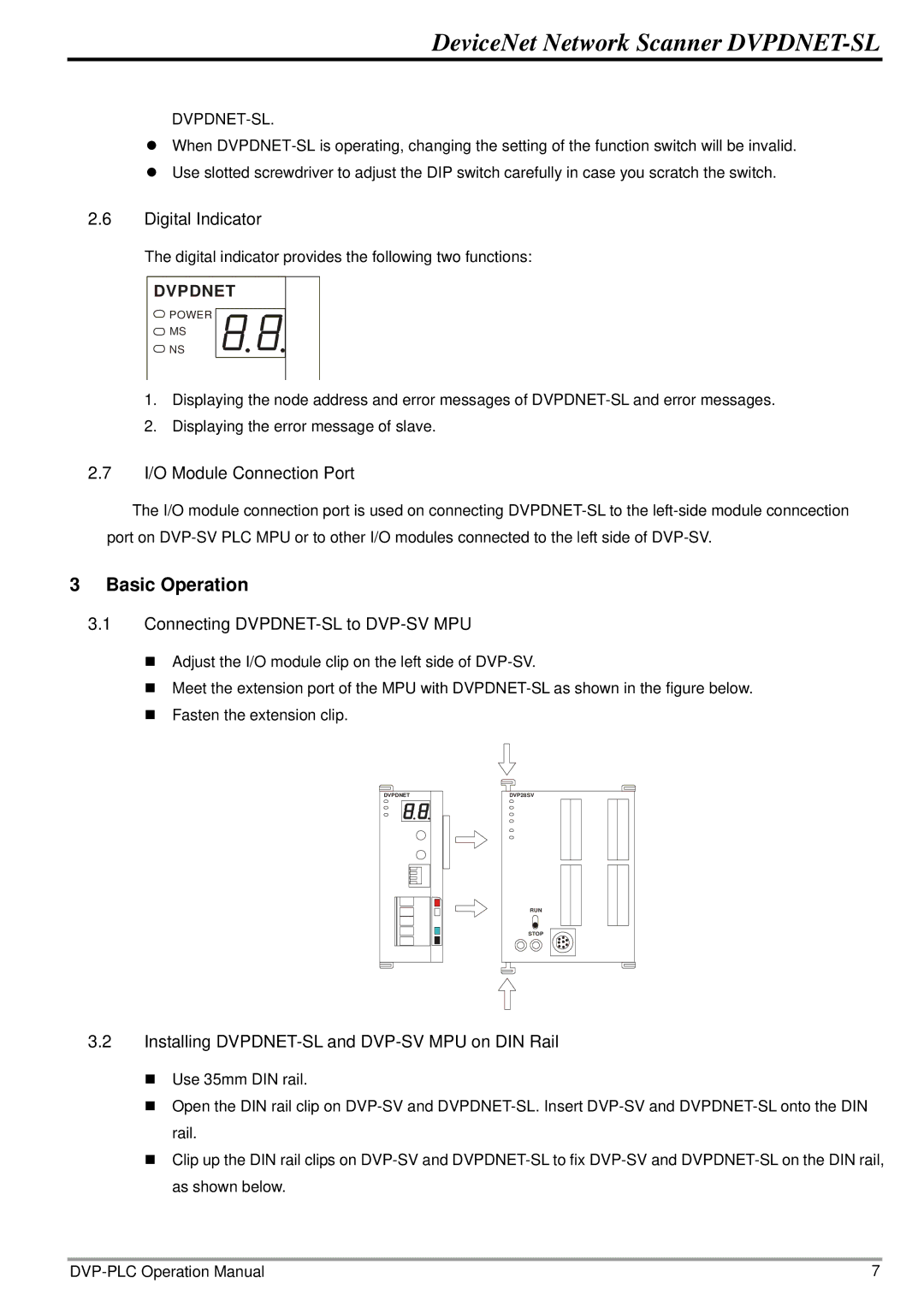
3.1Connecting DVPDNET-SL to DVP-SV MPU
Adjust the I/O module clip on the left side of
Meet the extension port of the MPU with
Fasten the extension clip.
DVPDNET | DVP28SV |
RUN
STOP
3.2Installing DVPDNET-SL and DVP-SV MPU on DIN Rail
Use 35mm DIN rail.
Open the DIN rail clip on
Clip up the DIN rail clips on
7 |