3Com
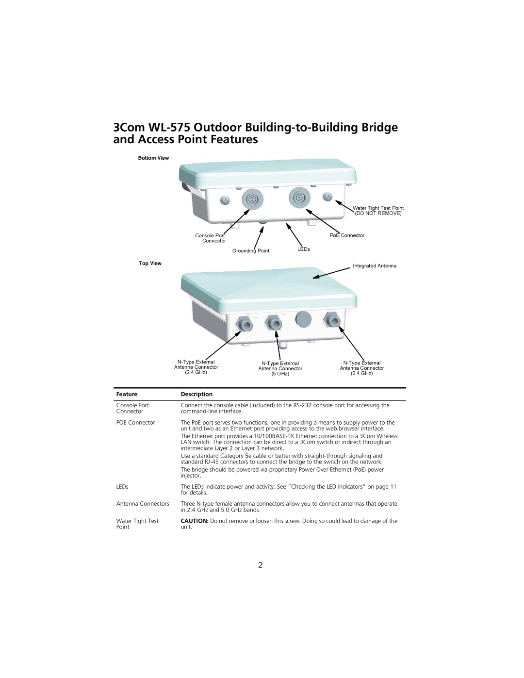
Bottom View
| Water Tight Test Point |
| (DO NOT REMOVE) |
Console Port | PoE Connector |
Connector |
|
Grounding Point | LEDs |
Top View | Integrated Antenna |
|
Antenna Connector | Antenna Connector | Antenna Connector |
(2.4 GHz) | (5 GHz) | (2.4 GHz) |
Feature | Description |
|
|
Console Port | Connect the console cable (included) to the |
Connector | |
POE Connector | The PoE port serves two functions, one in providing a means to supply power to the |
| unit and two as an Ethernet port providing access to the web browser interface. |
| The Ethernet port provides a |
| LAN switch. The connection can be direct to a 3Com switch or indirect through an |
| intermediate Layer 2 or Layer 3 network. |
| Use a standard Category 5e cable or better with |
| standard |
| The bridge should be powered via proprietary Power Over Ethernet (PoE) power |
| injector. |
LEDs | The LEDs indicate power and activity. See “Checking the LED Indicators” on page 11 |
| for details. |
Antenna Connectors | Three |
| in 2.4 GHz and 5.0 GHz bands. |
Water Tight Test | CAUTION: Do not remove or loosen this screw. Doing so could lead to damage of the |
Point | unit. |
2