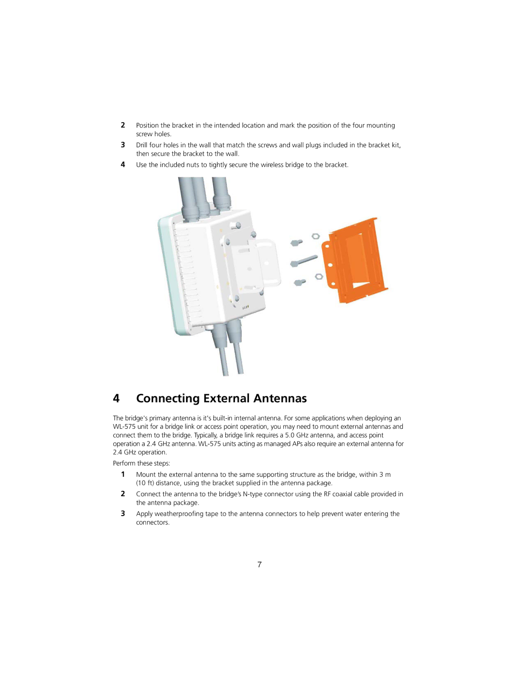
2Position the bracket in the intended location and mark the position of the four mounting screw holes.
3Drill four holes in the wall that match the screws and wall plugs included in the bracket kit, then secure the bracket to the wall.
4Use the included nuts to tightly secure the wireless bridge to the bracket.
4 Connecting External Antennas
The bridge's primary antenna is it's
2.4GHz operation. Perform these steps:
1Mount the external antenna to the same supporting structure as the bridge, within 3 m (10 ft) distance, using the bracket supplied in the antenna package.
2Connect the antenna to the bridge’s
3Apply weatherproofing tape to the antenna connectors to help prevent water entering the connectors.
7
