MANAGING THE MODULE
When the Module is installed, you can configure it through your Switch to add extra functionality. Refer to the documentation that accompanies your Switch 4300.
The Switch 4300 dynamically assigns port numbers to each Module installed, so if you add, replace or remove a Module, the port number of the other Module may change. The port numbers allocated depend on the type of Module; the number of Modules installed and the slots into which they are fitted.
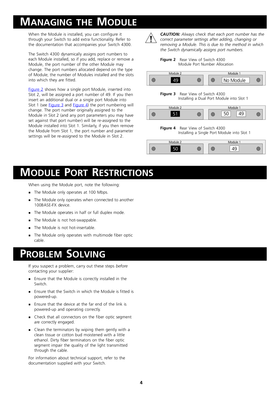
Figure 2 shows how a single port Module, inserted into Slot 2, will be assigned a port number of 49. If you then insert an additional dual or a single port Module into Slot 1 (see Figure 3 and Figure 4) the port numbering will change. The port number originally assigned to the Module in Slot 2 (and any port parameters you may have set against that port number) will be re-assigned to the Module installed into Slot 1. Similarly, if you then remove the Module from Slot 1, the port number and parameter settings will be re-assigned to the Module in Slot 2.
CAUTION: Always check that each port number has the correct parameter settings after adding, changing or removing a Module. This is due to the method in which the Switch dynamically assigns port numbers.
Figure 2 Rear View of Switch 4300
Module Port Number Allocation
Figure 3 Rear View of Switch 4300
Installing a Dual Port Module into Slot 1
Figure 4 Rear View of Switch 4300
Installing a Single Port Module into Slot 1
MODULE PORT RESTRICTIONS
When using the Module port, note the following:
The Module only operates at 100 Mbps.
The Module only operates when connected to another
The Module operates in half or full duplex mode.
The Module is not
TThe Module is not
The Module only operates with multimode fiber optic cable.
PROBLEM SOLVING
If you suspect a problem, carry out these steps before contacting your supplier:
Ensure that the Module is correctly installed in the
Switch.
Ensure that the Switch in which the Module is fitted is
Ensure that the device at the far end of the link is
Check that all connectors on the fiber optic segment
Tare correctly engaged.
Clean the terminators by wiping them gently with a clean tissue or cotton bud moistened with a little ethanol. Dirty fiber terminators on the fiber optic segment impair the quality of the light transmitted through the cable.
For information about technical support, refer to the documentation supplied with your Switch.
4