MODEL 2100 OVERHEAD PROJECTOR
1.Select a 60 by 60 inch, smooth area on one wall. Place a sturdy bench or test stand about 8 feet from this wall area. Position the Overhead Projector on the test stand so that it points toward the wall.
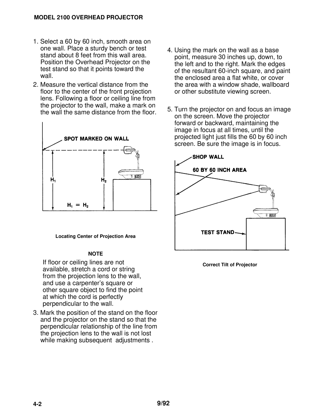
2.Measure the vertical distance from the floor to the center of the front projection lens. Following a floor or ceiling line from the projector to the wall, make a mark on the wall the same distance from the floor.
4.Using the mark on the wall as a base point, measure 30 inches up, down, to the left and to the right. Mark the edges of the resultant
5.Turn the projector on and focus an image on the screen. Move the projector forward or backward, maintaining the image in focus at all times, until the projected light just fills the 60 by 60 inch screen. Be sure the image is in focus.
Locating Center of Projection Area
NOTE
If floor or ceiling lines are not | Correct Tilt of Projector | |
available, stretch a cord or string | ||
| ||
from the projection lens to the wall, |
| |
and use a carpenter’s square or |
| |
other square object to find the point |
| |
at which the cord is perfectly |
| |
perpendicular to the wall. |
|
3.Mark the position of the stand on the floor and the projector on the stand so that the perpendicular relationship of the line from the projection lens to the wall is not lost while making subsequent adjustments .
9/92 |