3M 2250E, 2273E manual cable path Red leg

Models: 2273E 2250E

1 24
Download 24 pages 52.76 Kb
Page 16
Image 16
cable path

The Receiver bar graph is visible on the right side (green). This indicates that the fault is ahead of the operator in the direction of the green-banded leg. Continue along the cable path, reinserting the frame probes every few steps while watching the Receiver bar graph.

When the bar graph is visible on the left side (red), the fault has been passed and is now behind the operator.

Move back, inserting the frame every few inches, until the bar graph returns to the green side. Turn the frame ninety degrees to the cable path. The fault is located beneath the center of the frame when the bar graph changes from one side to the other.

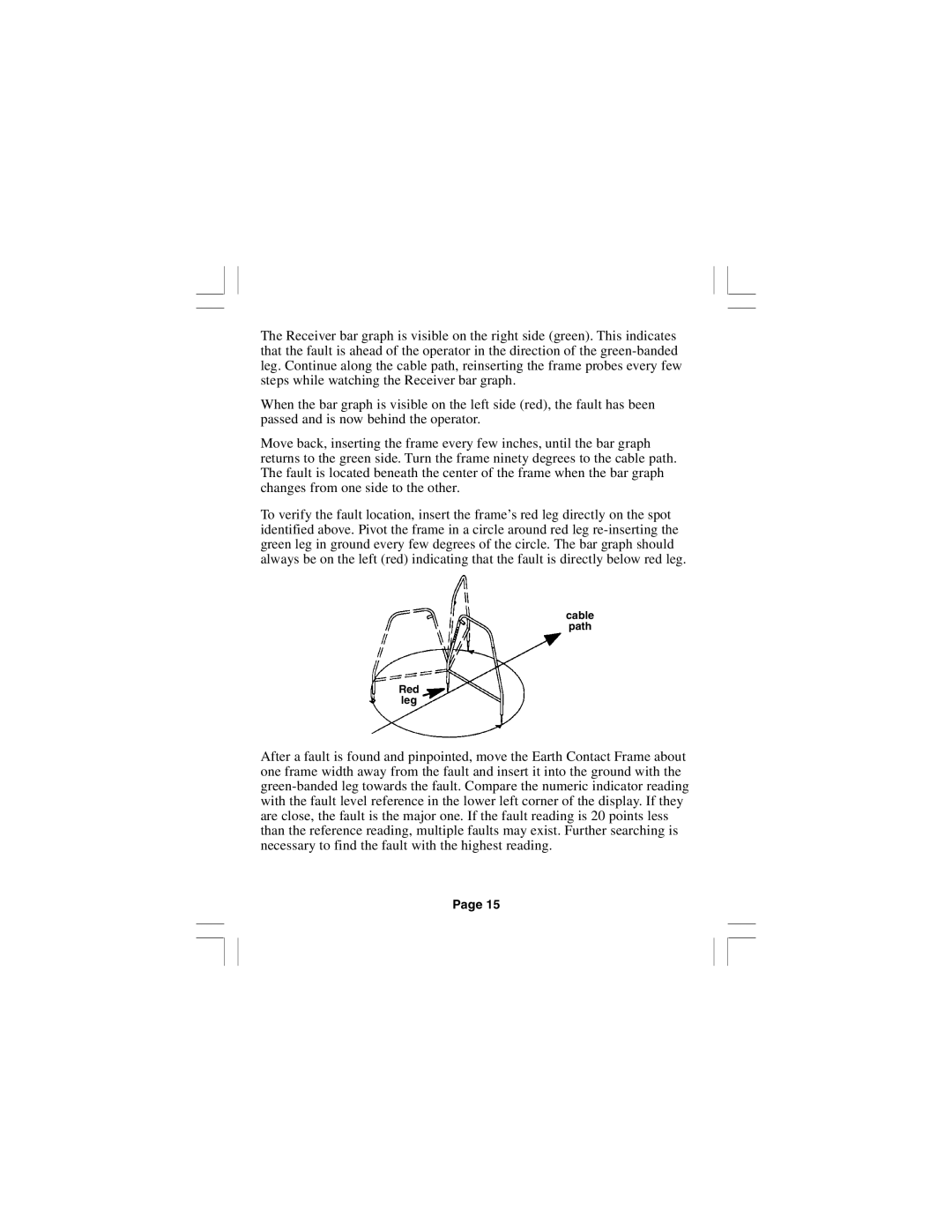
To verify the fault location, insert the frame’s red leg directly on the spot identified above. Pivot the frame in a circle around red leg re-inserting the green leg in ground every few degrees of the circle. The bar graph should always be on the left (red) indicating that the fault is directly below red leg.

cable path

Red leg

After a fault is found and pinpointed, move the Earth Contact Frame about one frame width away from the fault and insert it into the ground with the green-banded leg towards the fault. Compare the numeric indicator reading with the fault level reference in the lower left corner of the display. If they are close, the fault is the major one. If the fault reading is 20 points less than the reference reading, multiple faults may exist. Further searching is necessary to find the fault with the highest reading.

Page 15

Page 16
Image 16
3M 2250E, 2273E manual cable path Red leg