Instructions for Wire Shielded Cable
7.0Prepare Cable
7.1Check to be sure cable size fits within kit range as shown in Table 1.
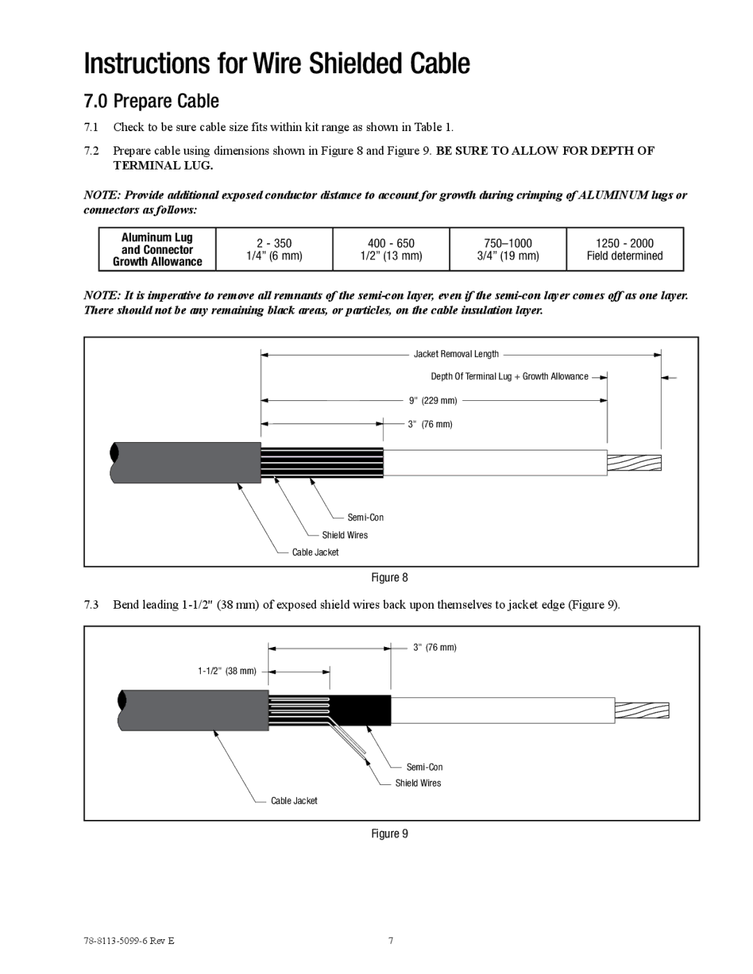
7.2Prepare cable using dimensions shown in Figure 8 and Figure 9. BE SURE TO ALLOW FOR DEPTH OF
TERMINAL LUG.
NOTE: Provide additional exposed conductor distance to account for growth during crimping of ALUMINUM lugs or connectors as follows:
Aluminum Lug | 2 - 350 | 400 - 650 | 1250 - 2000 | ||
and Connector | |||||
1/4” (6 mm) | 1/2” (13 mm) | 3/4” (19 mm) | Field determined | ||
Growth Allowance | |||||
|
|
|
| ||
|
|
|
|
|
NOTE: It is imperative to remove all remnants of the
Jacket Removal Length |
Depth Of Terminal Lug + Growth Allowance |
9" (229 mm) |
3" (76 mm) |
Shield Wires |
Cable Jacket |
Figure 8
7.3Bend leading
3" (76 mm) |
Shield Wires |
Cable Jacket |
Figure 9
7 |