2.0 Instructions for Tape Shielded Cable
Prepare Cable
2.1Check to be sure cable size fits within kit range as shown in Table 1.
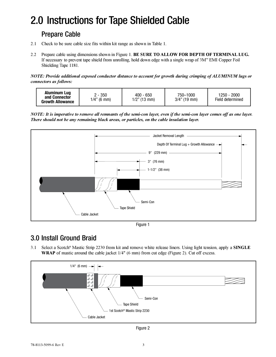
2.2Prepare cable using dimensions shown in Figure 1. BE SURE TO ALLOW FOR DEPTH OF TERMINAL LUG. If necessary to prevent tape shield from unrolling, hold down edge with a single wrap of 3M™ EMI Copper Foil Shielding Tape 1181.
NOTE: Provide additional exposed conductor distance to account for growth during crimping of ALUMINUM lugs or connectors as follows:
Aluminum Lug | 2 - 350 | 400 - 650 |
| 1250 - 2000 | |
and Connector | |||||
1/4” (6 mm) | 1/2” (13 mm) | 3/4” (19 mm) | Field determined | ||
Growth Allowance | |||||
|
|
|
| ||
|
|
|
|
|
NOTE: It is imperative to remove all remnants of the
Jacket Removal Length |
Depth Of Terminal Lug + Growth Allowance |
9" (229 mm) |
3" (76 mm) |
Tape Shield |
Cable Jacket |
Figure 1
3.0Install Ground Braid
3.1Select a Scotch® Mastic Strip 2230 from kit and remove white release liners. Using light tension, apply a SINGLE
WRAP of mastic around the cable jacket 1/4" (6 mm) from cut edge (Figure 2). Cut off excess.
1/4" (6 mm) |
Tape Shield |
1st Scotch® Mastic Strip 2230 |
Cable Jacket |
Figure 2
3 |