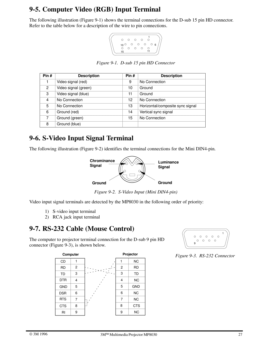
9-5. Computer Video (RGB) Input Terminal
The following illustration (Figure
1
10 | 6 |
1511
Figure 9-1. D-sub 15 pin HD Connector
Pin #
1
2
3
4
5
6
7
8
Description
Video signal (red)
Video signal (green)
Video signal (blue)
No Connection
No Connection
Ground (red)
Ground (green)
Ground (blue)
Pin #
9
10
11
12
13
14
15
Description
No Connection
Ground
Ground
No Connection
Horizontal/composite sync signal
Vertical sync signal
No Connection
9-6. S-Video Input Signal Terminal
The following illustration (Figure
Chrominance | Luminance | |
Signal | ||
Signal | ||
| ||
Ground | Ground |
Figure 9-2. S-Video Input (Mini DIN4-pin)
Video input signal terminals are detected by the MP8030 in the following order of priority:
1)
2)RCA jack input terminal
9-7. RS-232 Cable (Mouse Control)
The computer to projector terminal connection for the
1
9
Computer
CD | 1 |
|
|
RD | 2 |
|
|
TD | 3 |
|
|
DTR | 4 |
|
|
GND | 5 |
|
|
DSR | 6 |
|
|
RTS | 7 |
|
|
CTS | 8 |
|
|
RI | 9 |
|
|
Projector
1NC
2RD
3TD
4NC
5GND
6NC
7NC
8CTS
9NC
Figure 9-3. RS-232 Connector
3M 1996 | 3M | | Multimedia Projector MP8030 | 27 |
|
|