FIGURE 11
B.ALL AIR FROM OUTDOORS: (See Figures 12, 13 and 14)
The confined space should be provided with two permanent openings, one commencing within 12 in. (30cm) of the top and one commencing within 12 in. (30cm) from the bottom of the enclosure. The openings should communicate directly, or by ducts, with the outdoors or spaces (crawl or attic) that freely communicate with the outdoors.
1.When directly communicating with the outdoors, each opening should have a minimum free area of 1 square inch per 4,000 Btu per hour (5.5 cm2/kW) of total input rating of all equipment in the enclosure (see Figure 12).
FIGURE 13
4.When ducts are used, they should be of the same
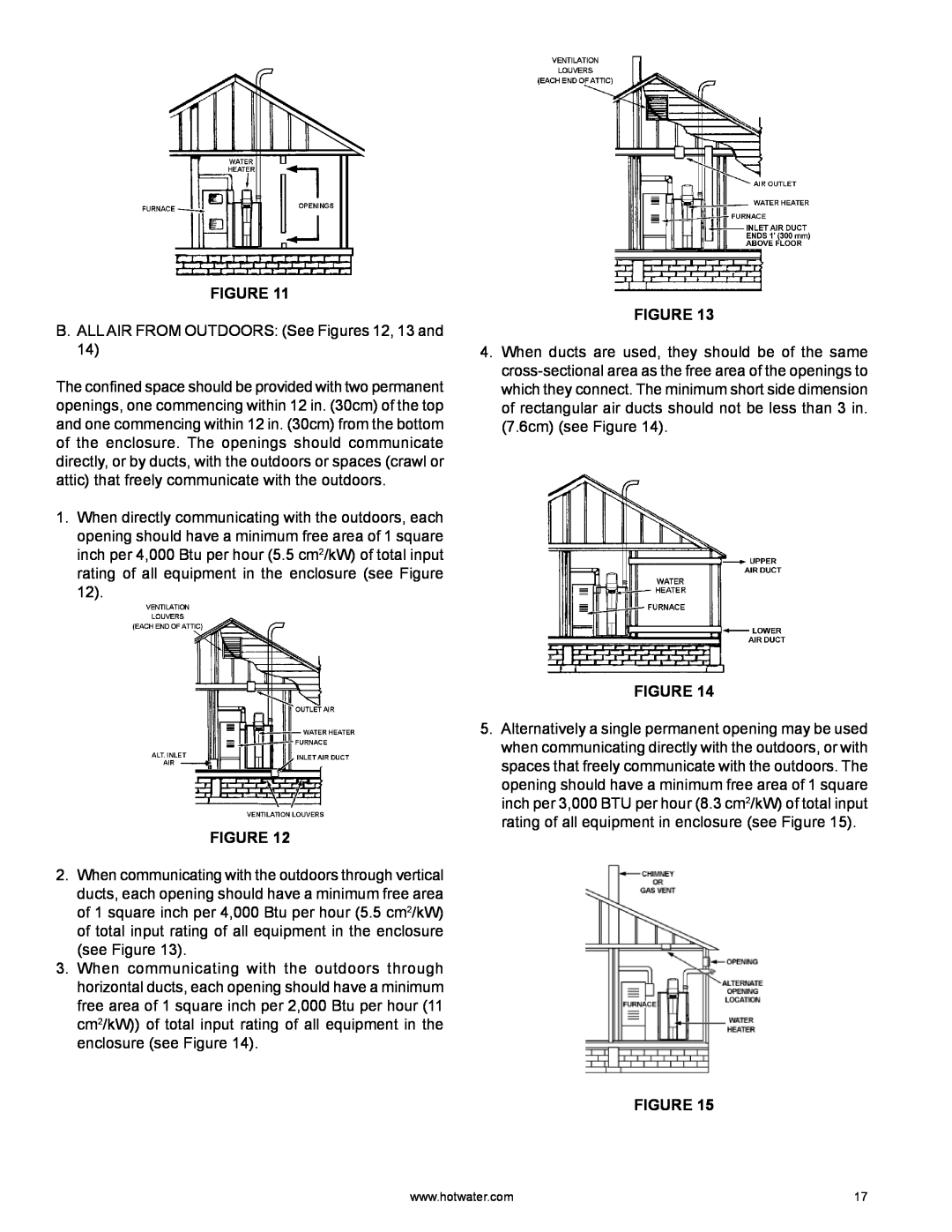
FIGURE 12
2.When communicating with the outdoors through vertical ducts, each opening should have a minimum free area of 1 square inch per 4,000 Btu per hour (5.5 cm2/kW) of total input rating of all equipment in the enclosure (see Figure 13).
3.When communicating with the outdoors through horizontal ducts, each opening should have a minimum free area of 1 square inch per 2,000 Btu per hour (11 cm2/kW)) of total input rating of all equipment in the enclosure (see Figure 14).
FIGURE 14
5.Alternatively a single permanent opening may be used when communicating directly with the outdoors, or with spaces that freely communicate with the outdoors. The opening should have a minimum free area of 1 square inch per 3,000 BTU per hour (8.3 cm2/kW) of total input rating of all equipment in enclosure (see Figure 15).
FIGURE 15
www.hotwater.com | 17 |