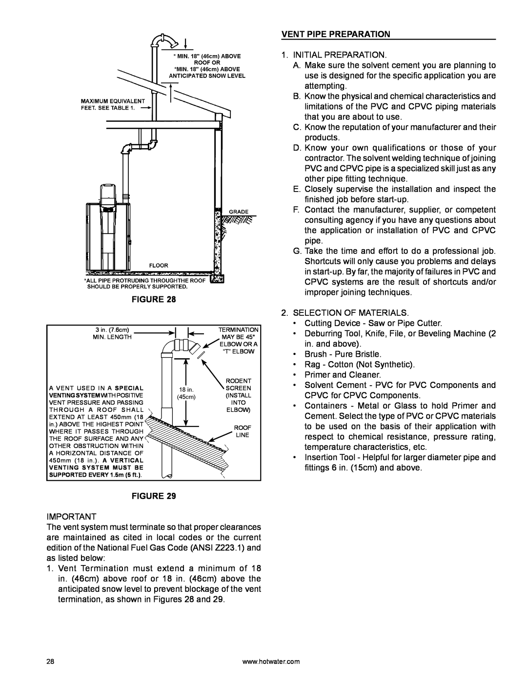
FIGURE 28
VENT PIPE PREPARATION
1. INITIAL PREPARATION. |
A. Make sure the solvent cement you are planning to |
use is designed for the specific application you are |
attempting. |
B. Know the physical and chemical characteristics and |
limitations of the PVC and CPVC piping materials |
that you are about to use. |
C. Know the reputation of your manufacturer and their |
products. |
D. Know your own qualifications or those of your |
contractor. The solvent welding technique of joining |
PVC and CPVC pipe is a specialized skill just as any |
other pipe fitting technique. |
E. Closely supervise the installation and inspect the |
finished job before |
F. Contact the manufacturer, supplier, or competent |
consulting agency if you have any questions about |
the application or installation of PVC and CPVC |
pipe. |
G. Take the time and effort to do a professional job. |
Shortcuts will only cause you problems and delays |
in |
CPVC systems are the result of shortcuts and/or |
improper joining techniques. |
2. SELECTION OF MATERIALS. |
• Cutting Device - Saw or Pipe Cutter. |
3 in. (7.6cm)
MIN. LENGTH
A VENT USED IN A SPECIAL VENTING SYSTEM WITH POSITIVE VENT PRESSURE AND PASSING THROUGH A ROOF SHALL EXTEND AT LEAST 450mm (18 in.) ABOVE THE HIGHEST POINT WHERE IT PASSES THROUGH THE ROOF SURFACE AND ANY OTHER OBSTRUCTION WITHIN A HORIZONTAL DISTANCE OF 450mm (18 in.). A VERTICAL
VENTING SYSTEM MUST BE SUPPORTED EVERY 1.5m (5 ft.).
TERMINATION
MAY BE 45°
![]() ELBOW OR A
ELBOW OR A
“T” ELBOW
RODENT
18 in.SCREEN
(45cm) (INSTALL INTO
ELBOW)
ROOF
LINE
• Deburring Tool, Knife, File, or Beveling Machine (2 |
in. and above). |
• Brush - Pure Bristle. |
• Rag - Cotton (Not Synthetic). |
• Primer and Cleaner. |
• Solvent Cement - PVC for PVC Components and |
CPVC for CPVC Components. |
• Containers - Metal or Glass to hold Primer and |
Cement. Select the type of PVC or CPVC materials |
to be used on the basis of their application with |
respect to chemical resistance, pressure rating, |
temperature characteristics, etc. |
• Insertion Tool - Helpful for larger diameter pipe and |
fittings 6 in. (15cm) and above. |
FIGURE 29
IMPORTANT
The vent system must terminate so that proper clearances are maintained as cited in local codes or the current edition of the National Fuel Gas Code (ANSI Z223.1) and as listed below:
1.Vent Termination must extend a minimum of 18 in. (46cm) above roof or 18 in. (46cm) above the anticipated snow level to prevent blockage of the vent termination, as shown in Figures 28 and 29.
28 | www.hotwater.com |
