The
No valve or other obstruction is to be placed between the relief valve and the tank. Do not connect tubing directly to discharge drain unless a 6 in. (15cm) air gap is provided. To prevent bodily injury, hazard to life, or property damage, the relief valve must be allowed to discharge water in quantities should circumstances demand. If the discharge pipe is not connected to a drain or other suitable means, the water flow may cause property damage.
The Discharge Pipe:
•Shall not be smaller in size than the outlet pipe size of the valve, or have any reducing couplings or other restrictions.
•Shall not be plugged or blocked.
•Shall be of material listed for hot water distribution.
•Shall be installed so as to allow complete drainage of both the
•Shall terminate a maximum of 6 in. (15cm) above a floor drain or external to the building. In cold climates, it is recommended that the discharge line be terminated at an adequate drain inside the building.
•Shall not have any valve between the relief valve and tank.
The
FIGURE 17
If after manually operating the valve, it fails to completely reset and continues to release water, immediately close the cold water inlet to the water heater, follow the draining instructions, and replace the
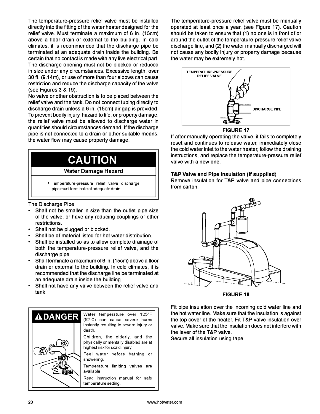
T&P Valve and Pipe Insulation (if supplied)
Remove insulation for T&P valve and pipe connections from carton.
FIGURE 18
Fit pipe insulation over the incoming cold water line and the hot water line. Make sure that the insulation is against the top cover of the heater. Fit T&P valve insulation over valve. Make sure that the insulation does not interfere with the lever of the T&P valve.
Secure all insulation using tape.
20 | www.hotwater.com |