Flame Sense Rod | Blower |
Water Valve
|
|
| YELLOW |
|
|
|
|
|
|
|
|
|
|
|
|
|
|
|
|
|
|
|
|
|
|
|
|
|
|
|
| M | BLUE | BLUE |
|
|
|
|
|
|
|
|
|
|
|
|
|
|
|
|
| RED | BLUE | YELLOW | BROWN |
|
|
|
|
|
| RED |
|
|
|
|
|
|
|
|
|
|
|
|
|
|
|
|
|
|
|
|
| ||||||
|
|
| BLACK |
|
|
|
|
|
|
|
|
|
|
|
|
|
|
|
|
|
|
|
|
|
|
|
|
|
|
|
|
| WHITE |
|
|
|
|
|
|
|
|
|
|
|
|
|
|
|
|
|
|
|
|
|
|
|
|
|
|
|
|
| BROWN |
|
|
|
|
|
|
|
|
|
|
|
|
|
|
|
|
|
|
|
|
|
|
|
|
|
|
|
|
|
|
| J1 |
|
|
|
|
|
|
|
|
|
|
|
|
|
|
|
|
|
|
|
| Thermal Fuse | Thermal Fuse | ||
|
|
|
|
| Flame |
|
|
| J6 |
|
|
|
|
|
|
|
|
|
|
| 1 | 2 | 3 | 4 |
|
|
|
| |
|
|
|
|
|
|
|
|
|
|
|
|
|
|
|
|
|
|
|
|
|
|
|
|
|
|
| |||
|
|
|
|
|
| J5 |
|
| 1 |
|
|
|
|
|
|
|
|
|
|
|
|
|
|
|
| J3 |
| RED | |
|
| Water Flow Sensor |
|
|
|
|
| Programing |
|
|
|
|
|
|
|
|
|
|
|
|
| J2 |
|
| 1 | RED | |||
|
| 1 | 6 | Water Valve |
|
|
|
|
|
|
|
|
|
|
|
|
|
|
|
|
|
|
|
| 2 |
| |||
|
|
|
| 2 | 7 | Water Flow |
|
|
|
|
|
|
|
|
|
|
|
|
|
|
|
| Blower |
|
|
|
| Power Transformer | |
|
|
|
| 3 | 8 |
|
|
|
|
|
|
|
|
|
|
|
|
|
|
|
|
|
|
|
|
|
|
|
|
|
|
| BLACK | 4 | 9 |
|
|
|
|
|
|
|
|
|
|
|
|
|
|
|
|
|
|
|
|
| J4 |
|
|
|
|
| YELLOW |
|
|
|
|
|
|
|
|
|
|
|
|
|
|
|
|
|
|
|
|
| 1 | BLUE | |||
|
|
| 5 | 10 |
|
|
| MCU |
|
|
|
|
|
|
|
|
|
|
|
|
|
|
|
|
| ||||
|
|
| RED |
|
|
|
|
|
|
|
|
|
|
|
|
|
|
|
|
|
|
| XFMR Sec | 2 | BLUE | ||||
|
|
|
|
|
|
|
|
| (Micro Controller) |
|
|
|
|
|
|
|
|
|
|
|
|
|
|
|
|
| 3 | BROWN | |
|
|
|
|
|
|
|
|
|
|
|
|
|
|
|
|
|
|
|
| J15 |
|
|
|
|
| BROWN | |||
|
|
|
|
|
|
|
|
|
|
|
|
|
|
|
|
|
|
|
|
|
|
|
|
|
|
| 4 | ||
|
|
|
|
|
| J8 |
|
|
|
|
|
|
|
|
|
|
|
|
|
|
|
|
|
|
|
| BLACK | ||
|
| Thermistors |
|
|
|
|
|
|
|
|
|
|
| J12 |
|
|
| Auxiliary Out/Igniter |
|
|
| 5 | |||||||
|
|
|
|
|
|
|
|
|
|
|
|
|
|
|
| J16 |
| J7 | BLACK | ||||||||||
|
| 1 | 4 |
|
|
|
|
|
|
|
|
|
|
|
|
| 6 | ||||||||||||
|
|
|
| 2 | 5 | Thermistors |
|
|
| J11 |
|
|
| Gas Valves / ECO |
|
|
|
|
| XFMR Pr | Power 120Vac |
|
| ||||||
|
| Inlet | BROWN |
|
|
|
|
|
|
|
|
|
|
|
|
|
| ||||||||||||
|
| 3 | 6 |
|
|
|
| High Temp SW |
|
|
|
|
|
|
|
|
| 4 |
|
| (Transformer) | 3 | 2 | 1 | 120 Vac | ||||
|
| BROWN |
|
|
|
|
|
|
|
|
|
|
|
|
|
|
| ||||||||||||
www.hotwater.com |
|
|
|
|
|
|
|
|
|
|
|
|
|
|
|
|
|
|
| J13 |
|
|
|
|
|
|
| BLACK | |
FIGURE34 |
| RED |
|
|
| J10 |
| SW1 |
|
|
|
|
| 7 | 8 |
| 9 |
| 3 |
|
| 3 |
|
|
|
| |||
|
|
|
|
|
|
|
|
|
|
|
|
| Pump |
|
|
|
|
| GREEN | ||||||||||
| BLACK | BLACK |
| BLUE |
| 1 | 2 | BLACK | YELLOW | GREY | BLUE BROWN | BLUE | BLACK | WHITE | WHITE | YELLOW | YELLOW |
|
|
| |||||||||
|
| BLUE |
|
| GREY | GREY | ORANGE | ORANGE |
|
|
| ||||||||||||||||||
|
| Outlet | RED |
|
| J9 |
|
|
|
|
|
|
|
|
|
|
|
|
|
|
|
|
|
|
|
| |||
|
|
|
|
| RS 485 | UIM |
| Setting |
|
|
|
|
| 4 | 5 |
| 6 |
| 2 |
|
|
|
|
|
|
|
| GREEN | |
|
|
|
|
|
|
|
|
|
|
|
|
|
|
|
|
| 2 |
|
| 2 | Fuse |
| |||||||
|
|
|
|
| 1 |
| 2 |
|
|
|
|
|
|
|
|
|
|
|
| 1 |
| 1 |
|
| 1 | F1 |
| ||
|
|
|
|
|
|
| 1 |
|
|
|
|
|
|
| 1 | 2 |
| 3 |
|
|
|
|
|
|
|
|
|
|
|
|
|
|
|
|
|
|
|
|
|
|
|
|
|
|
|
|
|
|
|
|
|
|
|
|
|
|
|
| BLACK |
|
|
|
|
|
|
|
|
|
|
|
|
|
|
|
|
|
|
|
|
|
|
|
|
|
|
|
|
| WHITE |
|
|
|
|
|
|
|
|
|
|
|
|
|
|
|
|
|
|
|
|
| Pump |
|
|
|
|
|
|
|
|
|
|
|
|
|
|
| 4 | 5 | 6 |
|
|
|
|
|
|
|
|
|
|
| M |
|
| Igniter |
|
|
|
| |
|
|
|
|
|
|
|
|
|
|
|
|
|
|
|
|
|
|
| ECO |
| GREEN |
|
|
|
|
|
|
|
|
|
|
|
|
|
|
| 1 | 2 | 3 |
|
|
|
|
|
|
|
|
|
|
|
|
|
|
|
|
|
|
|
|
|
|
|
|
|
|
|
|
|
|
|
| Main |
| 1st | 2nd | Prop |
|
|
|
|
|
|
|
|
|
|
|
|
|
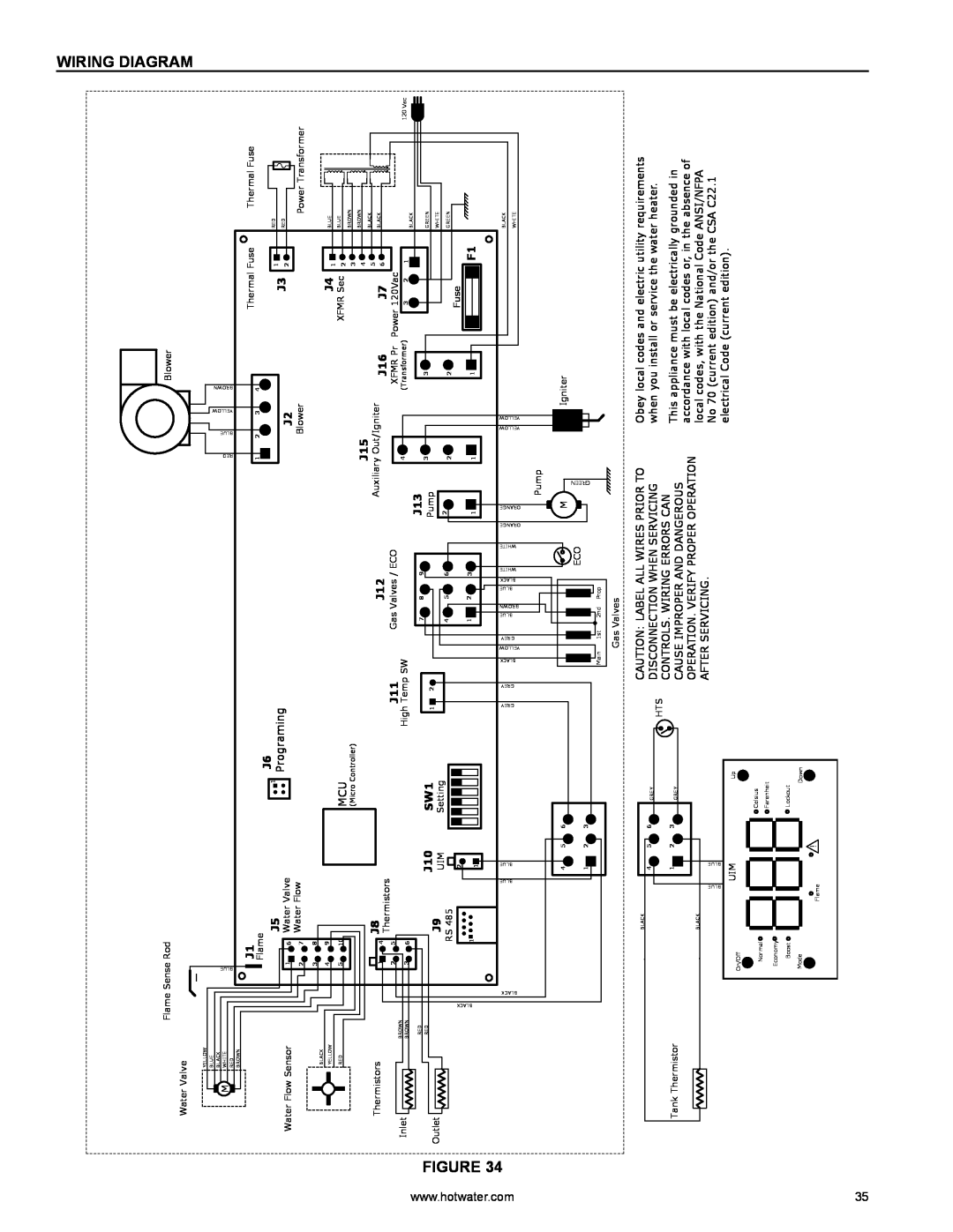
WIRING DIAGRAM
|
|
|
|
|
| Gas Valves |
BLACK |
|
|
|
|
| CAUTION: LABEL ALL WIRES PRIOR TO |
| 4 | 5 | 6 | GREY |
| DISCONNECTION WHEN SERVICING |
|
|
|
| HTS | ||
|
|
|
|
| CONTROLS. WIRING ERRORS CAN | |
Tank Thermistor | 1 | 2 | 3 |
|
| |
GREY |
| CAUSE IMPROPER AND DANGEROUS | ||||
|
|
|
| |||
|
|
|
|
|
| |
BLACK |
|
|
|
|
| OPERATION. VERIFY PROPER OPERATION |
|
|
|
|
| AFTER SERVICING. | |
BLUE | BLUE |
|
|
|
| |
|
|
|
|
| ||
On/Off | UIM |
|
| Up |
|
|
|
|
|
|
|
| |
Normal |
|
|
| Celsius |
|
|
|
|
| Farenheit |
|
| |
|
|
|
|
|
| |
Economy |
|
|
|
|
|
|
Boost |
|
|
| Lockout |
|
|
Mode |
|
|
| Down |
|
|
Flame |
| ! |
|
|
|
|
|
|
|
|
|
|
Obey local codes and electric utility requirements when you install or service the water heater.
This appliance must be electrically grounded in accordance with local codes or, in the absence of local codes, with the National Code ANSI/NFPA No 70 (current edition) and/or the CSA C22.1 electrical Code (current edition).
35