| 6 in. (15 cm) |
|
|
|
| |||
| MIN. LENGTH |
|
|
|
|
| ||
| ATTACH 45° |
|
|
| SEALANT | |||
|
|
|
|
| ||||
| TERMINATION |
|
|
|
| |||
|
| ELBOW |
|
|
|
| ||
|
|
|
|
|
|
| VENT PIPING TO BE | |
|
| RODENT |
|
|
| SLOPED (DOWN) | ||
|
|
|
|
| ||||
|
|
|
|
| TOWARD HEATER | |||
|
| SCREEN |
|
|
| |||
|
|
|
|
| TO PREVENT WATER | |||
|
| (INSTALL |
|
|
| |||
12 in. | INTO |
|
|
| FROM COLLECTING. | |||
SEALANT | ||||||||
(30 cm) min. | ELBOW) | |||||||
|
| GROUND | ||||||
|
|
| LEVEL* | |||||
*WHERE SNOW COVER IS NORMALDURING WINTER, ENSURE SUFFICIENT VENT CLEARANCE TO PREVENT BLOCKAGE OR ICE BUILDUP.
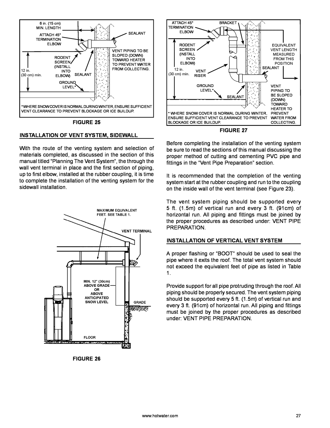
FIGURE 25
INSTALLATION OF VENT SYSTEM, SIDEWALL
With the route of the venting system and selection of materials completed, as discussed in the section of this manual titled “Planning The Vent System”, the through the wall vent terminal in place and the first section of piping, up to first elbow, installed at the rubber coupling, it is time to complete the installation of the venting system for the sidewall installation.
FIGURE 26
| ATTACH 45° |
|
| BRACKET |
|
|
| |||
TERMINATION |
|
|
|
|
|
|
| |||
|
| ELBOW |
|
|
|
|
|
|
| |
|
|
|
|
|
|
|
|
|
| |
|
| RODENT |
|
|
|
|
|
| ||
|
|
|
|
| EQUIVALENT | |||||
|
| SCREEN |
|
|
| VENT LENGTH | ||||
|
| (INSTALL |
|
|
| MEASURED | ||||
|
| INTO |
|
|
| FROM THIS | ||||
|
| ELBOW) |
|
|
| POSITION | ||||
|
|
|
|
|
|
| SEALANT |
|
| |
|
| 12 in. |
|
| VENT | |||||
(30 cm) min. |
|
|
|
|
|
|
| |||
| RISER |
|
|
|
|
| ||||
|
|
|
|
|
|
|
|
| ||
|
|
|
|
| GROUND |
|
| VENT | ||
|
|
|
|
| LEVEL* |
|
| PIPING TO | ||
|
|
|
|
|
|
| SEALANT | BE SLOPED | ||
|
|
|
|
|
|
| (DOWN) | |||
|
|
|
|
|
|
|
| |||
|
|
|
|
|
|
|
| TOWARD | ||
* WHERE SNOW COVER IS NORMAL DURING WINTER, | HEATER TO | |||||||||
PREVENT | ||||||||||
ENSURE SUFFICIENT VENT CLEARANCE TO PREVENT | WATER FROM | |||||||||
BLOCKAGE OR ICE BUILDUP. | COLLECTING. | |||||||||
FIGURE 27
Before completing the installation of the venting system be sure to read the sections of this manual discussing the proper method of cutting and cementing PVC pipe and fittings in the “Vent Pipe Preparation” section.
It is recommended that the completion of the venting system start at the rubber coupling and run to the coupling on the inside wall of the vent terminal (see Figure 23).
The vent system piping should be supported every 5 ft. (1.5m) of vertical run and every 3 ft. (91cm) of horizontal run. All piping and fittings must be joined by the proper procedures as described under: VENT PIPE PREPARATION.
INSTALLATION OF VERTICAL VENT SYSTEM
A proper flashing or “BOOT” should be used to seal the pipe where it exits the roof. The total vent system should not exceed the equivalent feet of pipe as listed in Table 1.
Provide support for all pipe protruding through the roof. All piping should be properly secured. The vent system piping should be supported every 5 ft. (1.5m) of vertical run and every 3 ft. (91cm) of horizontal run. All piping and fittings must be joined by the proper procedures as described under: VENT PIPE PREPARATION.
www.hotwater.com | 27 |