Chapter 2 | |
|
|
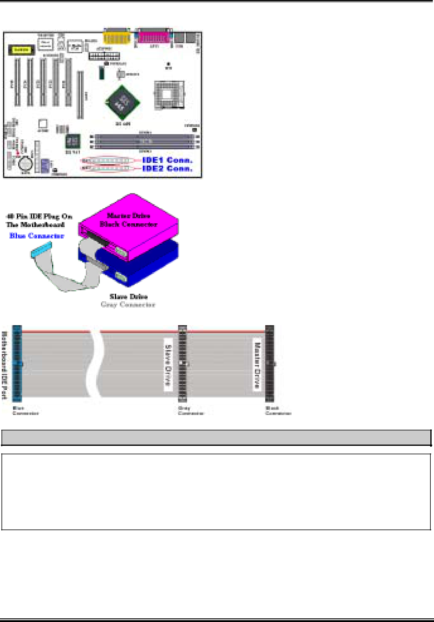
(10). IDE1and IDE2 Connectors
This motherboard provides two IDE ports (IDE1 & IDE2) to connect up to four IDE devices in Ultra DMA 100 mode by Ultra DMA 66 ribbon cables. Each cable has
If you want to connect two hard drives together through one IDE channel, you must configure the second drive to Slave mode after the first Master
drive. Please refer to the HDD documentation for jumper settings. The first drive connected to IDE1 is usually referred to as “Primary Master”, and the second drive as “Primary Slave”. The first drive connected to IDE2 is referred to as “Secondary Master” and the second drive as “Secondary Slave”.
Keep away from connecting one legacy slow speed device, like
Figure
Ribbon Cable Outline
Note
!The Master or Slave status of the hard disk drive is set on the hard disk itself. Please refer to the hard disk drive user’s manual.
!To connect Ultra DMA 100 devices on IDE1and IDE2, an Ultra DMA 66 cable is required.
!A red mark on a wire typically designates the location of pin 1. You need to align the wire pin 1 to the IDE connector pin 1 before inserting the wire connector into the IDE connector.