SYSTEM INTERCONNECTIONS
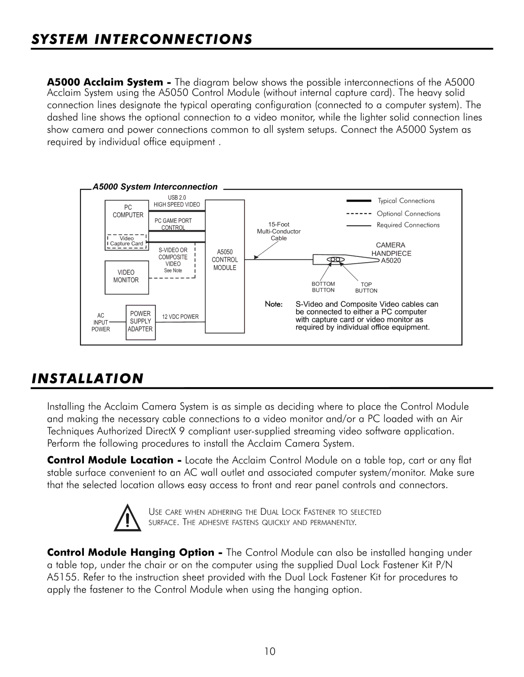
A5000 Acclaim System - The diagram below shows the possible interconnections of the A5000 Acclaim System using the A5050 Control Module (without internal capture card). The heavy solid
connection lines designate the typical operating configuration (connected to a computer system). The dashed line shows the optional connection to a video monitor, while the lighter solid connection lines show camera and power connections common to all system setups. Connect the A5000 System as required by individual office equipment .
A5000 System Interconnection
|
| USB 2.0 |
|
|
PC | HIGH SPEED VIDEO |
|
| |
|
|
| ||
COMPUTER | PC GAME PORT |
|
| |
|
|
|
| |
|
| CONTROL |
|
|
Video |
|
|
| |
Capture Card |
|
| A5050 | |
|
|
| ||
|
| |||
|
| COMPOSITE |
| CONTROL |
|
| VIDEO |
| MODULE |
VIDEO | See Note |
| ||
|
| |||
|
|
| ||
MONITOR |
|
|
| |
|
|
|
|
|
AC | POWER | 12 VDC POWER | |
SUPPLY | |||
INPUT |
| ||
POWER | ADAPTER |
| |
|
|
|
| Typical Connections |
| Optional Connections |
Required Connections | |
| |
Cable |
|
| CAMERA |
| HANDPIECE |
| A5020 |
BOTTOMTOP
BUTTON BUTTON
Note:
INSTALLATION
Installing the Acclaim Camera System is as simple as deciding where to place the Control Module and making the necessary cable connections to a video monitor and/or a PC loaded with an Air Techniques Authorized DirectX 9 compliant
Control Module Location - Locate the Acclaim Control Module on a table top, cart or any flat stable surface convenient to an AC wall outlet and associated computer system/monitor. Make sure that the selected location allows easy access to front and rear panel controls and connectors.
USE CARE WHEN ADHERING THE DUAL LOCK FASTENER TO SELECTED
SURFACE. THE ADHESIVE FASTENS QUICKLY AND PERMANENTLY.
Control Module Hanging Option - The Control Module can also be installed hanging under a table top, under the chair or on the computer using the supplied Dual Lock Fastener Kit P/N A5155. Refer to the instruction sheet provided with the Dual Lock Fastener Kit for procedures to apply the fastener to the Control Module when using the hanging option.
10