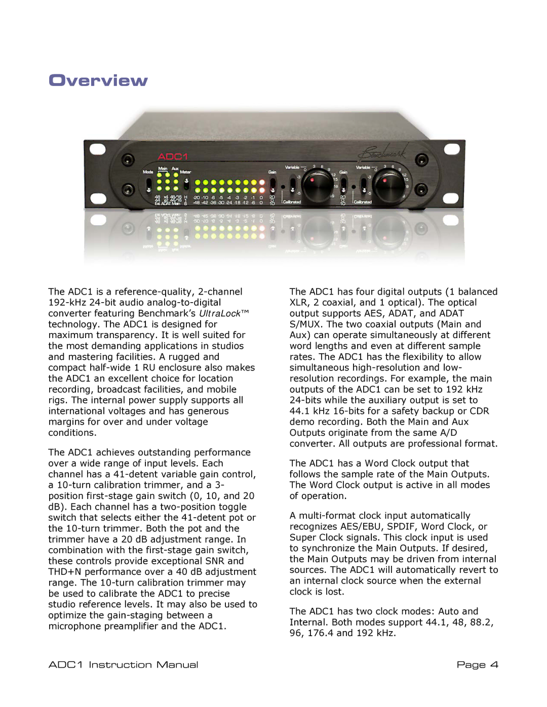
The ADC1 is a reference-quality, 2-channel 192-kHz 24-bit audio analog-to-digital converter featuring Benchmark’s UltraLock™ technology. The ADC1 is designed for maximum transparency. It is well suited for the most demanding applications in studios and mastering facilities. A rugged and compact half-wide 1 RU enclosure also makes the ADC1 an excellent choice for location recording, broadcast facilities, and mobile rigs. The internal power supply supports all international voltages and has generous margins for over and under voltage conditions.
The ADC1 achieves outstanding performance over a wide range of input levels. Each channel has a 41-detent variable gain control, a 10-turn calibration trimmer, and a 3- position first-stage gain switch (0, 10, and 20 dB). Each channel has a two-position toggle switch that selects either the 41-detent pot or the 10-turn trimmer. Both the pot and the trimmer have a 20 dB adjustment range. In combination with the first-stage gain switch, these controls provide exceptional SNR and THD+N performance over a 40 dB adjustment range. The 10-turn calibration trimmer may be used to calibrate the ADC1 to precise studio reference levels. It may also be used to optimize the gain-staging between a microphone preamplifier and the ADC1.
ADC1 Instruction Manual
The ADC1 has four digital outputs (1 balanced XLR, 2 coaxial, and 1 optical). The optical output supports AES, ADAT, and ADAT S/MUX. The two coaxial outputs (Main and Aux) can operate simultaneously at different word lengths and even at different sample rates. The ADC1 has the flexibility to allow simultaneous high-resolution and low- resolution recordings. For example, the main outputs of the ADC1 can be set to 192 kHz 24-bits while the auxiliary output is set to
44.1kHz 16-bits for a safety backup or CDR demo recording. Both the Main and Aux Outputs originate from the same A/D converter. All outputs are professional format.
The ADC1 has a Word Clock output that follows the sample rate of the Main Outputs. The Word Clock output is active in all modes of operation.
Amulti-format clock input automatically recognizes AES/EBU, SPDIF, Word Clock, or Super Clock signals. This clock input is used to synchronize the Main Outputs. If desired, the Main Outputs may be driven from internal sources. The ADC1 will automatically revert to an internal clock source when the external clock is lost.
The ADC1 has two clock modes: Auto and Internal. Both modes support 44.1, 48, 88.2, 96, 176.4 and 192 kHz.
Page 4

