6Beneath the Screens field, click the ‘+’ button to display the Add Screen dialog so that you can add a new screen (computer system):
10You now need to define the positional relationships between the various screens of the systems, using the lower part of the Screens & Links window.
e? | 7 In the ‘Screen Name’ field, enter the ‘Hostname’ (see step 4) of one of the | |
computer systems and choose the corresponding ‘Switch Number’ (its port | ||
| ||
| number on the Adder TS4 unit). | |
| You can optionally use the other controls within this dialog: | |
| Aliases - Enter one or more unique names that you would prefer to use for | |
| the system. | |
| Dead Corners - This option allows you to define one or more corner regions | |
| of the screen where you need to prevent switching to another screen. This is | |
| most often used in the corner where the Windows Start button is located so | |
| that you do not accidentally switch screens. Check one or more of the boxes | |
| to select the appropriate corner(s) and use the ‘Size‘ field to define a square | |
| area (side length of the square in pixels, extending out from the corner) in | |
| which switching should be disabled. |
11Use the drop down controls (ringed in red), to select the border (left, right, top or bottom) of a screen, and the screen to which it should switch, e.g.
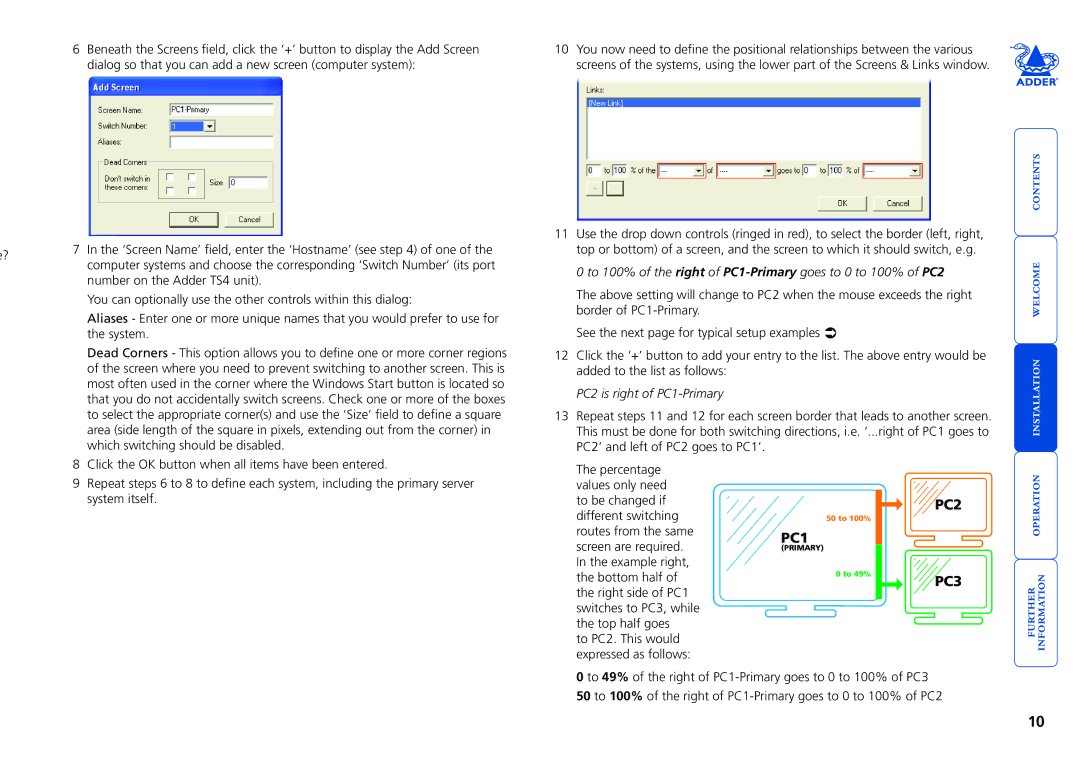
0 to 100% of the right of PC1-Primary goes to 0 to 100% of PC2
The above setting will change to PC2 when the mouse exceeds the right border of
See the next page for typical setup examples Ü
12Click the ‘+’ button to add your entry to the list. The above entry would be added to the list as follows:
PC2 is right of PC1-Primary
13Repeat steps 11 and 12 for each screen border that leads to another screen. This must be done for both switching directions, i.e. ‘...right of PC1 goes to PC2’ and left of PC2 goes to PC1’.
8 | Click the OK button when all items have been entered. |
9 | Repeat steps 6 to 8 to define each system, including the primary server |
| system itself. |
The percentage values only need to be changed if different switching routes from the same screen are required. In the example right, the bottom half of the right side of PC1 switches to PC3, while the top half goes
to PC2. This would expressed as follows:
PC2
50 to 100%
PC1
(PRIMARY)
0 to 49% | PC3 |
|
0 to 49% of the right of
10