
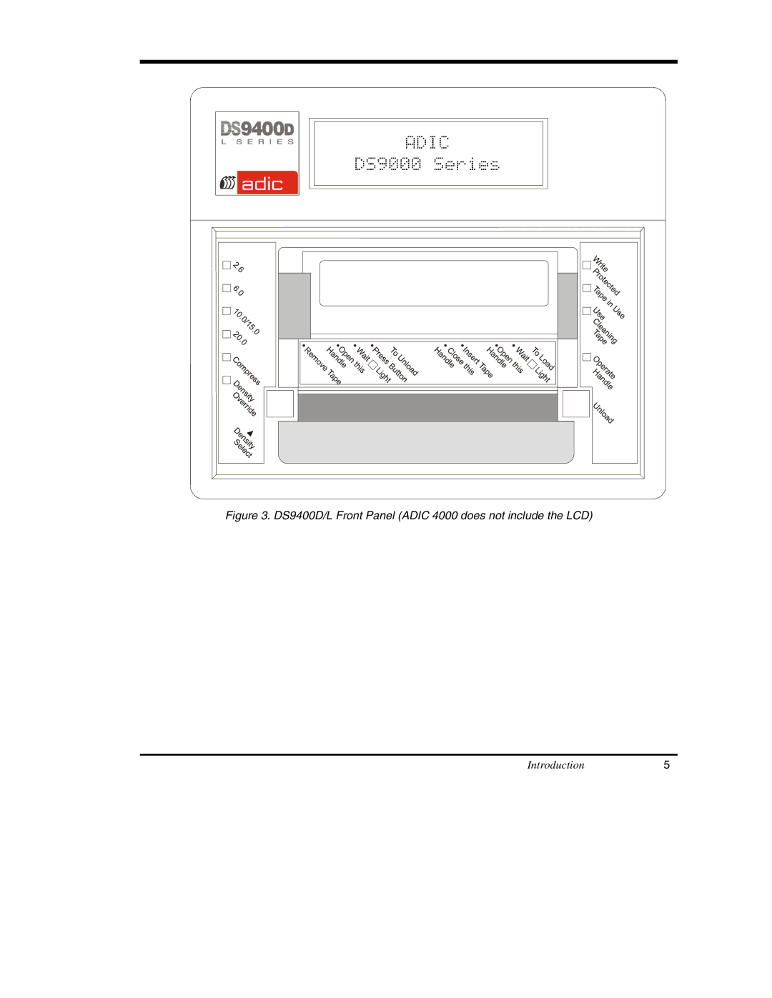
DS9000 Series specifications
The ADIC DS9000 Series is a robust storage solution designed to meet the demanding requirements of enterprise environments. Known for its high-performance capabilities, this series of products offers features that cater specifically to data-intensive applications, making it a preferred choice for organizations looking to optimize their data management strategies.One of the main features of the ADIC DS9000 Series is its scalability. The architecture allows businesses to start with a configuration that meets their current needs, with the flexibility to expand as data storage requirements grow. This adaptability makes it suitable for various industries, including finance, healthcare, and media, where data volumes continuously increase.
Another significant characteristic is its advanced data protection mechanisms. The DS9000 incorporates features such as RAID support, which enhances data redundancy and reduces the risk of data loss. This is crucial for enterprises that rely on the availability of their data around the clock. Furthermore, the system supports automated backup and recovery processes, ensuring that critical data remains safe and can be quickly restored in case of an emergency.
The DS9000 Series leverages cutting-edge technologies, including high-speed connectivity options such as Fibre Channel and iSCSI. These technologies enable fast data transfer rates and lower latency, which are essential for real-time applications and high-throughput environments. Enhanced performance is achieved through optimized caching techniques and intelligent management of read/write operations, contributing to an overall efficient data handling experience.
Additionally, the ADIC DS9000 focuses on energy efficiency. The design incorporates features that reduce power consumption, which is an important consideration for organizations seeking to minimize operational costs. Coupled with a modular design, the series not only provides high performance but also ensures easy maintenance and upgrades, further extending the lifespan of the storage solutions.
In terms of management, the DS9000 Series offers intuitive software tools that allow administrators to monitor performance, manage storage resources effectively, and automate routine tasks. This ease of management is a critical aspect that allows IT teams to allocate their time towards strategic initiatives rather than being bogged down by routine maintenance.
Overall, the ADIC DS9000 Series stands out as a comprehensive storage solution that marries performance, scalability, and reliability to cater to the evolving needs of modern enterprises. Its advanced features and technologies position it as a leader in the storage market, making it an ideal choice for organizations aiming to harness the power of their data.