Chapter 2 Installing and Removing Power Components
How to Install or Remove Modular Configuration Power Components
Installing DC Terminal Block Covers
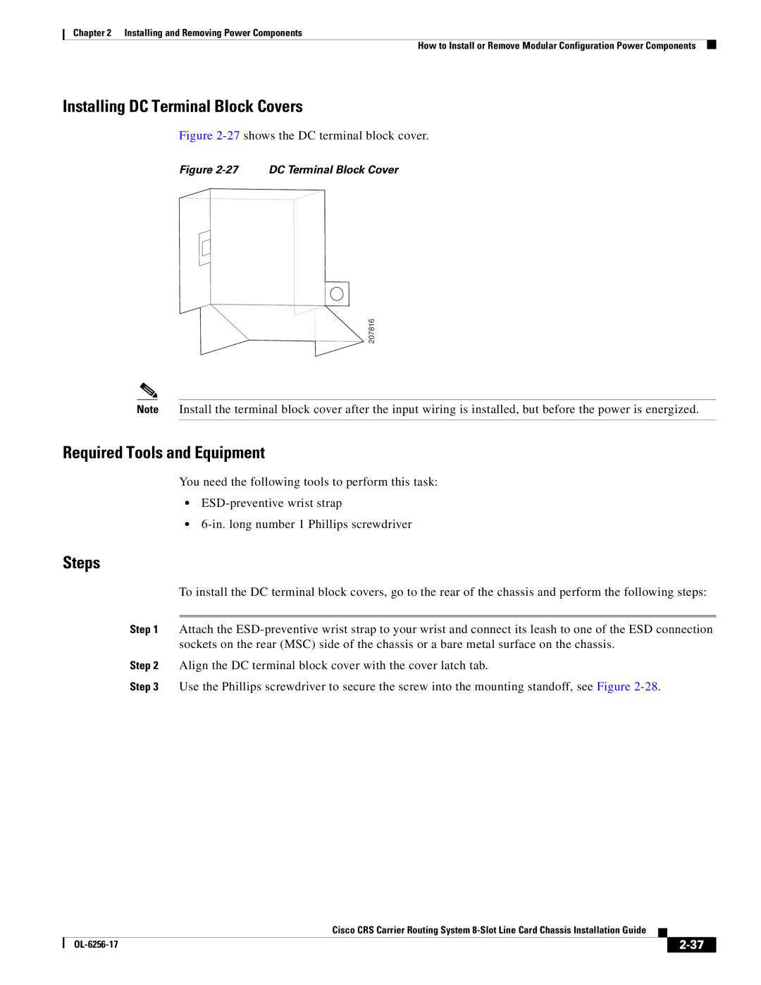
Figure 2-27 shows the DC terminal block cover.
Figure 2-27 DC Terminal Block Cover
207816
Note Install the terminal block cover after the input wiring is installed, but before the power is energized.
Required Tools and Equipment
You need the following tools to perform this task:
•
•
Steps
To install the DC terminal block covers, go to the rear of the chassis and perform the following steps:
Step 1 Attach the
Step 2 Align the DC terminal block cover with the cover latch tab.
Step 3 Use the Phillips screwdriver to secure the screw into the mounting standoff, see Figure
Cisco CRS Carrier Routing System
|
| ||
|
|