Chapter 2 Installing and Removing Power Components
How to Install or Remove Modular Configuration Power Components
Steps
To remove the wiring from the modular configuration DC power shelf, perform the following steps:
Step 1 Attach the
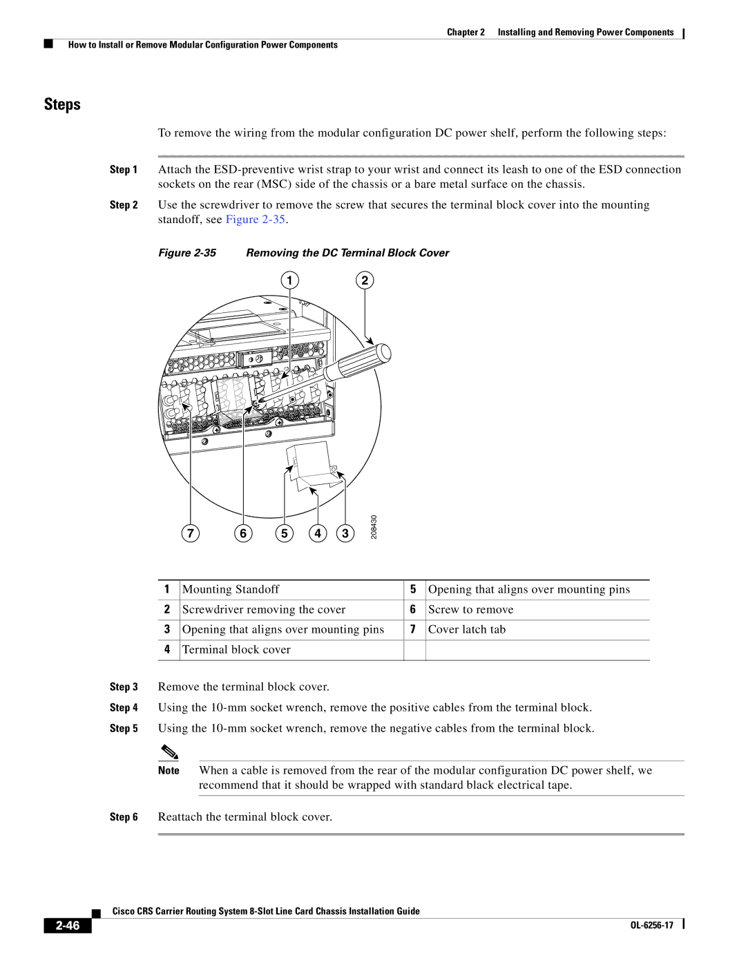
Step 2 Use the screwdriver to remove the screw that secures the terminal block cover into the mounting standoff, see Figure
Figure 2-35 Removing the DC Terminal Block Cover
12
7 | 6 | 5 | 4 | 3 |
208430
1 | Mounting Standoff | 5 | Opening that aligns over mounting pins |
|
|
|
|
2 | Screwdriver removing the cover | 6 | Screw to remove |
|
|
|
|
3 | Opening that aligns over mounting pins | 7 | Cover latch tab |
|
|
|
|
4 | Terminal block cover |
|
|
|
|
|
|
Step 3 Remove the terminal block cover.
Step 4 Using the
Note When a cable is removed from the rear of the modular configuration DC power shelf, we recommend that it should be wrapped with standard black electrical tape.
Step 6 Reattach the terminal block cover.
Cisco CRS Carrier Routing System
|
| |
|