Chapter 1 Cisco CRS Carrier Routing System
Chassis Cable Management
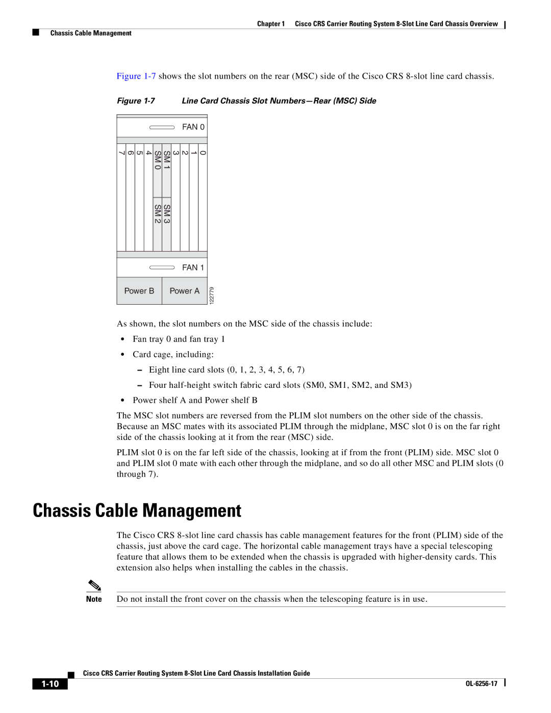
Figure 1-7 shows the slot numbers on the rear (MSC) side of the Cisco CRS 8-slot line card chassis.
Figure 1-7 Line Card Chassis Slot Numbers—Rear (MSC) Side
FAN 0
4 5 6 7 | SM | SM | 0 1 2 3 |
| 0 | 1 |
|
| SM 2 | SM 3 |
|
FAN 1
Power B | Power A |
| 122779 |
|
| ||
|
|
|
|
As shown, the slot numbers on the MSC side of the chassis include:
•Fan tray 0 and fan tray 1
•Card cage, including:
–Eight line card slots (0, 1, 2, 3, 4, 5, 6, 7)
–Four
•Power shelf A and Power shelf B
The MSC slot numbers are reversed from the PLIM slot numbers on the other side of the chassis. Because an MSC mates with its associated PLIM through the midplane, MSC slot 0 is on the far right side of the chassis looking at it from the rear (MSC) side.
PLIM slot 0 is on the far left side of the chassis, looking at if from the front (PLIM) side. MSC slot 0 and PLIM slot 0 mate with each other through the midplane, and so do all other MSC and PLIM slots (0 through 7).
Chassis Cable Management
The Cisco CRS
Note Do not install the front cover on the chassis when the telescoping feature is in use.
Cisco CRS Carrier Routing System
| ||
|