Chapter 3 Installing and Removing Air Circulation Components
How to Install or Remove Air Circulation Components
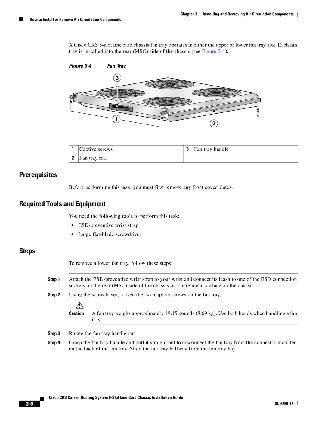
A Cisco CRS
Figure | Fan Tray |
3
1
2
1 Captive screws | 3 Fan tray handle |
2Fan tray rail
122289
Prerequisites
Before performing this task, you must first remove any front cover plates.
Required Tools and Equipment
You need the following tools to perform this task:
•
•Large
Steps
To remove a lower fan tray, follow these steps:
Step 1 Attach the
Step 2 Using the screwdriver, loosen the two captive screws on the fan tray.
Caution A fan tray weighs approximately 19.15 pounds (8.69 kg). Use both hands when handling a fan tray.
Step 3 Rotate the fan tray handle out.
Step 4 Grasp the fan tray handle and pull it straight out to disconnect the fan tray from the connector mounted on the back of the fan tray. Slide the fan tray halfway from the fan tray bay.
Cisco CRS Carrier Routing System
|
| |
|