Chapter 3 Installing and Removing Air Circulation Components
How to Install or Remove Air Circulation Components
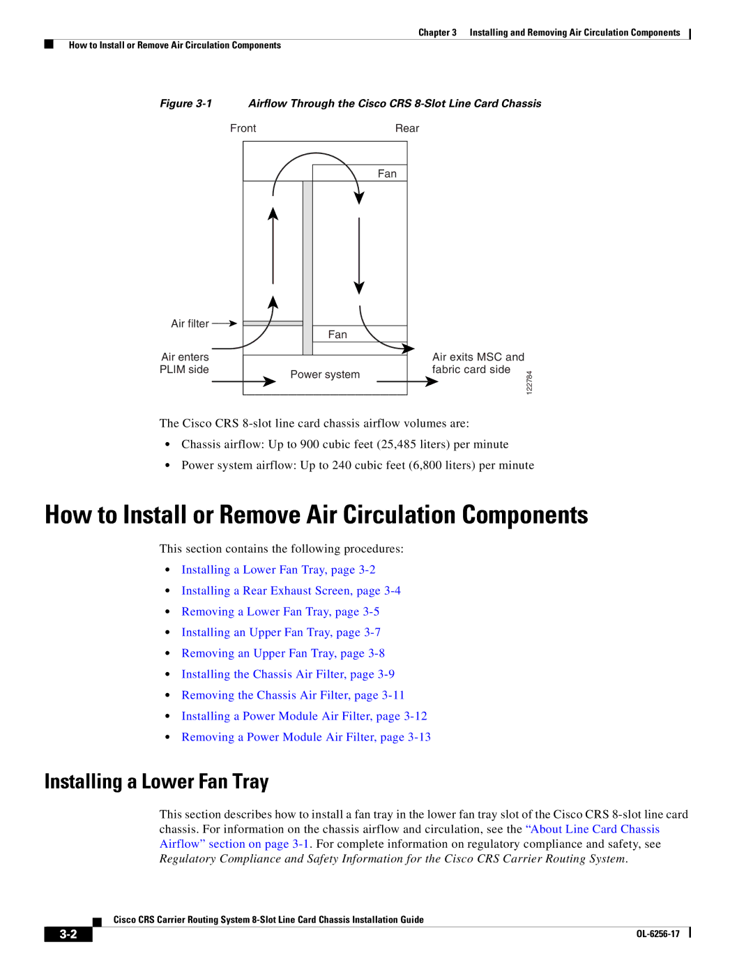
Figure 3-1 Airflow Through the Cisco CRS 8-Slot Line Card Chassis
Front | Rear |
| Fan |
Air filter | Fan |
| |
Air enters |
|
PLIM side | Power system |
|
Air exits MSC and fabric card side
122784
The Cisco CRS
•Chassis airflow: Up to 900 cubic feet (25,485 liters) per minute
•Power system airflow: Up to 240 cubic feet (6,800 liters) per minute
How to Install or Remove Air Circulation Components
This section contains the following procedures:
•Installing a Lower Fan Tray, page
•Installing a Rear Exhaust Screen, page
•Removing a Lower Fan Tray, page
•Installing an Upper Fan Tray, page
•Removing an Upper Fan Tray, page
•Installing the Chassis Air Filter, page
•Removing the Chassis Air Filter, page
•Installing a Power Module Air Filter, page
•Removing a Power Module Air Filter, page
Installing a Lower Fan Tray
This section describes how to install a fan tray in the lower fan tray slot of the Cisco CRS
Cisco CRS Carrier Routing System
|
| |
|