Chapter 2 Installing and Removing Power Components
Power Component Information Common to Two Types of Power System
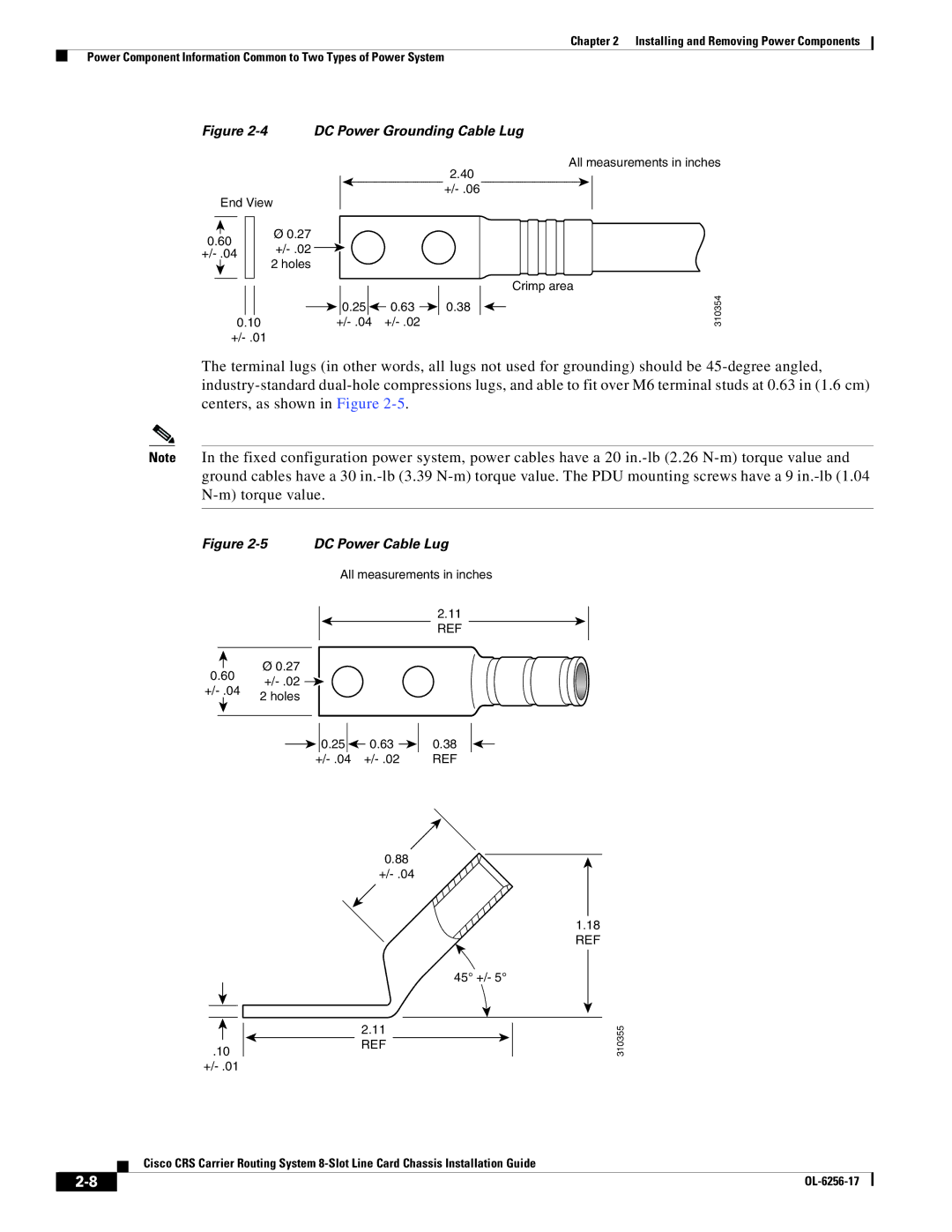
Figure 2-4 DC Power Grounding Cable Lug
2.40
End View
|
|
|
|
| Ø 0.27 |
|
|
|
|
| |
0.60 |
|
| |||
|
| ||||
|
| ||||
|
| 2 holes | |||
|
|
|
|
| |
|
|
|
|
|
|
![]()
![]() 0.25
0.25 ![]()
![]() 0.63
0.63 ![]()
![]() 0.38
0.38
0.10
All measurements in inches
Crimp area
310354
The terminal lugs (in other words, all lugs not used for grounding) should be
Note In the fixed configuration power system, power cables have a 20
Figure 2-5 DC Power Cable Lug
All measurements in inches
2.11 REF
Ø0.27
0.60
2 holes | |
|
| 0.25 |
|
| 0.63 |
|
| 0.38 |
|
| ||||||
| REF | ||||||
.10
0.88
45° +/- 5°
2.11 REF
1.18 REF
310355
Cisco CRS Carrier Routing System
|
| |
|