Chapter 2 Installing and Removing Power Components
How to Install or Remove Modular Configuration Power Components
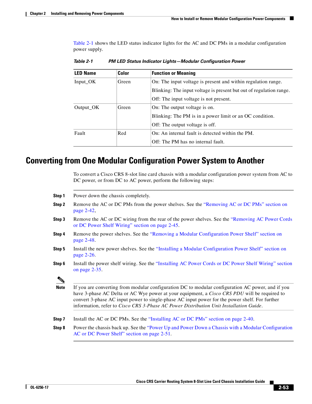
Table
Table | PM LED Status Indicator | ||
|
|
|
|
LED Name |
| Color | Function or Meaning |
|
|
|
|
Input_OK |
| Green | On: The input voltage is present and within regulation range. |
|
|
| Blinking: The input voltage is present but out of regulation range. |
|
|
| Off: The input voltage is not present. |
|
|
|
|
Output_OK |
| Green | On: The output voltage is on. |
|
|
| Blinking: The PM is in a power limit or an OC condition. |
|
|
| Off: The output voltage is off. |
|
|
|
|
Fault |
| Red | On: An internal fault is detected within the PM. |
|
|
| Off: The PM has no internal fault. |
|
|
|
|
Converting from One Modular Configuration Power System to Another
To convert a Cisco CRS
Step 1 Power down the chassis completely.
Step 2 Remove the AC or DC PMs from the power shelves. See the “Removing AC or DC PMs” section on page
Step 3 Remove the AC or DC wiring from the rear of the power shelves. See the “Removing AC Power Cords or DC Power Shelf Wiring” section on page
Step 4 Remove the power shelves. See the “Removing a Modular Configuration Power Shelf” section on page
Step 5 Install the new power shelves. See the “Installing a Modular Configuration Power Shelf” section on page
Step 6 Install the power shelf wiring. See the “Installing AC Power Cords or DC Power Shelf Wiring” section on page
Note If you are converting from modular configuration DC to modular configuration AC power, and if you have
Step 7 Install the AC or DC PMs. See the “Installing AC or DC PMs” section on page
Step 8 Power the chassis back up. See the “Power Up and Power Down a Chassis with a Modular Configuration AC or DC Power Shelf” section on page
Cisco CRS Carrier Routing System
|
| ||
|
|