Cisco Systems, Inc
Page
N T E N T S
Installing a Modular Configuration Power Shelf
Steps Installing DC Terminal Block Covers
Installing the Chassis Air Filter
Information About Small Form-Factor Pluggable SFP Modules
Verifying the Installation of a Switch Fabric Card
How to Install or Remove a Physical Layer Interface Module
Troubleshooting the Plim
Installing the Front Cover Prerequisites
Xii
Audience
Objective
Document Organization
Document Conventions
Changes to This Document
Related Documentation
Xvi
Obtaining Documentation and Submitting a Service Request
Xviii
Chassis Overview
Chassis Components
122775
CRS 8-Slot AC Rear CRS 8-Slot DC Rear
CRS 8-Slot AC Front CRS 8-Slot DC Front
281371
Rear MSC View of Line Card Chassis-Fixed Configuration Shown
Chassis Components
Line Card Chassis Slot Numbering-Front Plim Side
Chassis Slot Numbers
Line Card Chassis Slot Numbers-Rear MSC Side
Chassis Cable Management
8shows the cable management bracket
Chassis Cooling System
Safety Guidelines
Chassis Power System
Preventing Electrostatic Discharge
OL-6256-17
Power Systems Overview
Installing and Removing Power Components
Basic Chassis Power Details
Modular Configuration Power System
Fixed Configuration Power System
Precautions and Recommendations
Bonding and Grounding Guidelines
Prerequisites
How to Install the Chassis Ground Cable
Required Tools and Equipment
Steps
Fixed Configuration DC Power
DC Power Systems
Fixed Configuration DC PDU with Plastic Safety Cover
DC Power Grounding Cable Lug
Modular Configuration DC Power
Modular Configuration DC Power Shelf Wiring
45-Degree DC Power Cable Lug
AC Power Systems
Modular Configuration AC Power
Fixed Configuration AC Power
This section contains the following procedures
Before Powering the Chassis Up or Down
Install the new PDUs. See the Installing a PDU section on
Installing a PDU
Prerequisites
What to Do Next
Removing a PDU
Required Tools and Equipment
11 Fixed Configuration DC PDU Power Cable Connections
Installing DC PDU Cables
Required Tools and Equipment
Removing DC PDU Wiring
12 Fixed Configuration AC Wye Rectifier
Installing a DC PEM or AC Rectifier
Removing a DC PEM or AC rectifier
13 Fixed Configuration AC Wye Rectifier
What to Do Next
14 Modular Configuration AC Power Shelf, Front View
Installing a Modular Configuration Power Shelf
15 Modular Configuration AC Power Shelf, Rear View
16 Modular Configuration DC Power Shelf, Front View
18 Modular Configuration Power Shelf Cross Bracket
19 Removing Rear Mounting Bracket from Power Shelf
20 Attaching Rear Mounting Brackets
21 Fastening the Power Shelf to the Chassis
M6 nut/bolt to tighten Mm wrench
208425
Installing Modular Configuration DC Power Shelf Wiring
Installing AC Power Cords or DC Power Shelf Wiring
Prerequisites
27shows the DC terminal block cover
Installing DC Terminal Block Covers
28 Securing the DC Terminal Block Cover
Installing Modular Configuration AC Power Shelf Wiring
29 Inserting AC Cord into Cord Clamp
Installing AC or DC PMs
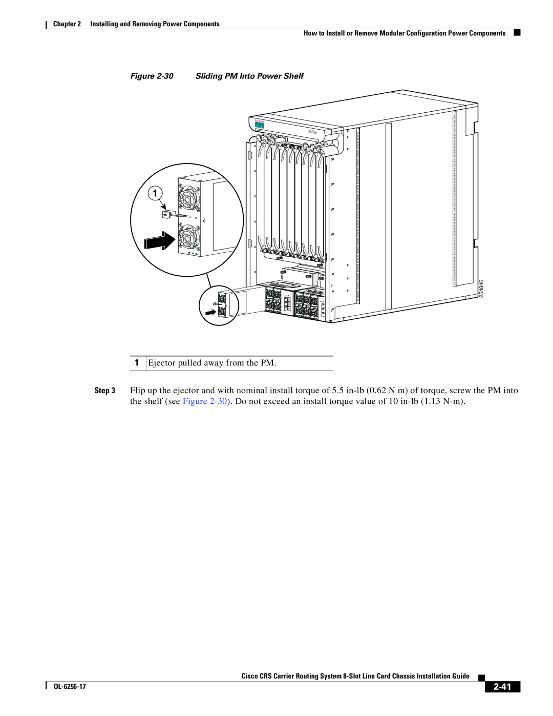
30 Sliding PM Into Power Shelf
31 Securing the Ejector Into the PM
Removing AC or DC PMs
32 Unscrew Ejectors from PM
Ejector on PM
Removing Modular Configuration DC Power Shelf Wiring
Removing AC Power Cords or DC Power Shelf Wiring
35 Removing the DC Terminal Block Cover
Removing Modular Configuration AC Power Shelf Wiring
36 Removing Cord from Cord Clamp
Removing a Modular Configuration Power Shelf
37 Loosening Nuts on Mounting Studs
Nut/bolt to remove Mm wrench
Screws that secure power shelf to chassis
Prerequisites
LED Name Color Function or Meaning
Remove the PDUs. See the Removing a PDU section on
About Line Card Chassis Airflow
Installing and Removing Air Circulation Components
Installing a Lower Fan Tray
How to Install or Remove Air Circulation Components
Captive screws Fan tray handle
Installing a Rear Exhaust Screen
Removing a Lower Fan Tray
Install rear exhaust screen
Captive screws Fan tray handle
Installing an Upper Fan Tray
Removing an Upper Fan Tray
Installing the Chassis Air Filter
Chassis Air Filter
Removing the Chassis Air Filter
Power Module Air Filter
Installing a Power Module Air Filter
Removing a Power Module Air Filter
Steps
A P T E R
Captive screw Ejector lever
Guidelines and Warnings for Card Installation and Removal
Operating Ejector Levers
Line Card Chassis Slot Numbers-Front Plim Side
Chassis Slot Numbers
Recommended Order of Card Installation
Information About Impedance Carriers and Slot Covers
Switch Fabric Slot Half Height Slot Cover
RP Slot Impedance Carrier
Plim Slot Impedance Carrier
MSC Slot Impedance Carrier
DRP Plim
DRP Card
Information About Hard Drives and Pcmcia Cards
Information About Small Form-Factor Pluggable SFP Modules
Information About Cable Management Brackets
Installing a Slot Cover
How to Install or Remove a Slot Cover
12 Switch Fabric Slot Half Height Slot Cover
Removing a Slot Cover
13 Switch Fabric Slot Half Height Slot Cover
Installing an Impedance Carrier
How to Install or Remove an Impedance Carrier
14 MSC Slot Impedance Carrier
Removing an Impedance Carrier
Installing a Pillow Block
How to Install or Remove a Pillow Block
Install the lower right screw see item number 3 in Figure
Removing a Pillow Block
Installing a Switch Fabric Card
How to Install or Remove a Switch Fabric Card
What’s Next
17 Switch Fabric Card
Captive screw Direction of installation or removal
Page
19 Switch Fabric Card
Removing a Switch Fabric Card
Before performing this task, remove any front cover plates
Troubleshooting the Switch Fabric Card
Verifying the Installation of a Switch Fabric Card
Understanding the Alphanumeric LEDs
Installing an MSC, FP, or LSP
How to Install or Remove an MSC, FP, or LSP
22 Modular Services Card CRS-MSC
Prerequisites Required Tools and Equipment
To install a line card, see -23and follow these steps
23 Installing an MSC
Removing an MSC, FP, or LSP
Prerequisites Required Tools and Equipment
24 Removing a Line Card
25is an illustration of the MSC-140G front panel
Verifying the Installation of an MSC, FP, or LSP
Status LEDs
Troubleshooting the MSC, FP, or LSP
Installing an RP, PRP, or DRP Card
How to Install or Remove an RP, PRP, or DRP Plim
28 Route Processor RP Card for the 8-Slot Chassis
Required Tools and Equipment
Removing an RP, PRP, or DRP Card
After performing this task, replace any front cover plates
Status LED
Verifying the Installation of an RP, PRP, or DRP Card
30shows the PRP card front panel
Troubleshooting the RP, PRP, or DRP Card
Installing a Pcmcia Card
How to Install or Remove a Pcmcia Card
Removing an RP Pcmcia Card
Installing a Plim
How to Install or Remove a Physical Layer Interface Module
245523
Plim
Installing a Plim
Removing a Plim
Required Tools and Equipment
34 Removing a Plim
Troubleshooting the Plim
Verifying the Installation of a Plim
36 Bale-Clasp SFP Module
Installing a Bale-Clasp SFP Module
Removing a Bale-Clasp SFP Module
37 Installing a Bale-Clasp SFP Module into a Port
38 Bale-Clasp SFP Module
39 Removing a Bale-Clasp SFP Module
Page
OL-6256-17
Overview of the Exterior Components
Installing and Removing Exterior Components
Removing the Cable Management Bracket
Reinstalling the Cable Management Bracket
Prerequisites
Installing the Inlet Grille-Fixed Configuration Power Supply
Steps
Inlet Grille-Modular Configuration Power Supply
No prerequisites exist for this task
Front Cover Installed on Chassis
Installing the Front Cover
279896
Removing the Front Cover
What to Do Next
P E N D I X a
Minimum torque In-lb 2.2 N-m Maximum torque In-lb 3.3 N-m
Description Value
Table A-2
Product IDs for the Cisco CRS 8-Slot Line Card Chassis
CRS-8-FRNT-GRILL=
CRS-8-FC-BLANK=
Optional Line Card, PLIM, SIP, and SPA Product IDs
CRS-LSP
20X10GBE-WL-XFP
SPA-OC192POS-XFP 64 POS/RPR XFP SPA