Chapter 2 Installing and Removing Power Components
Power Component Information Common to Two Types of Power System
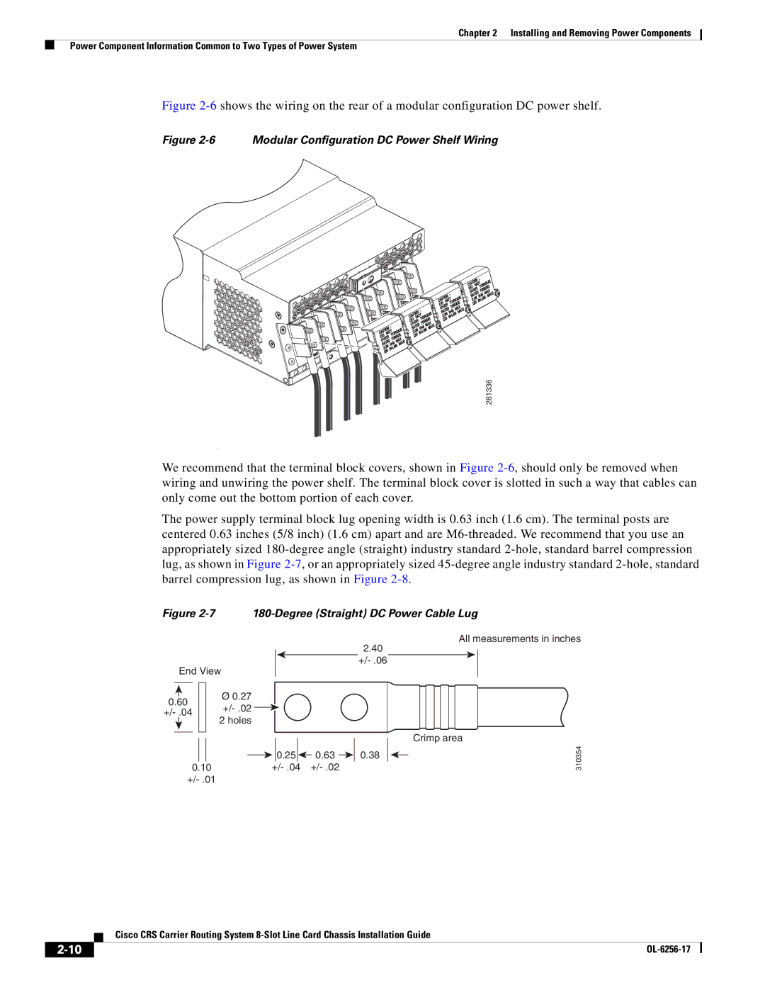
Figure 2-6 shows the wiring on the rear of a modular configuration DC power shelf.
Figure 2-6 Modular Configuration DC Power Shelf Wiring
281336
We recommend that the terminal block covers, shown in Figure
The power supply terminal block lug opening width is 0.63 inch (1.6 cm). The terminal posts are centered 0.63 inches (5/8 inch) (1.6 cm) apart and are
Figure 2-7 180-Degree (Straight) DC Power Cable Lug
2.40
End View
|
|
|
|
| Ø 0.27 |
|
|
|
|
| |
0.60 |
|
| |||
|
| ||||
|
| ||||
|
| 2 holes | |||
|
|
|
|
| |
|
|
|
|
|
|
![]()
![]() 0.25
0.25 ![]()
![]() 0.63
0.63 ![]()
![]() 0.38
0.38
0.10
All measurements in inches
Crimp area
310354
Cisco CRS Carrier Routing System
|
| |
|