Chapter 5 Installing and Removing Exterior Components
Installing or Removing the Front Side Exterior Components
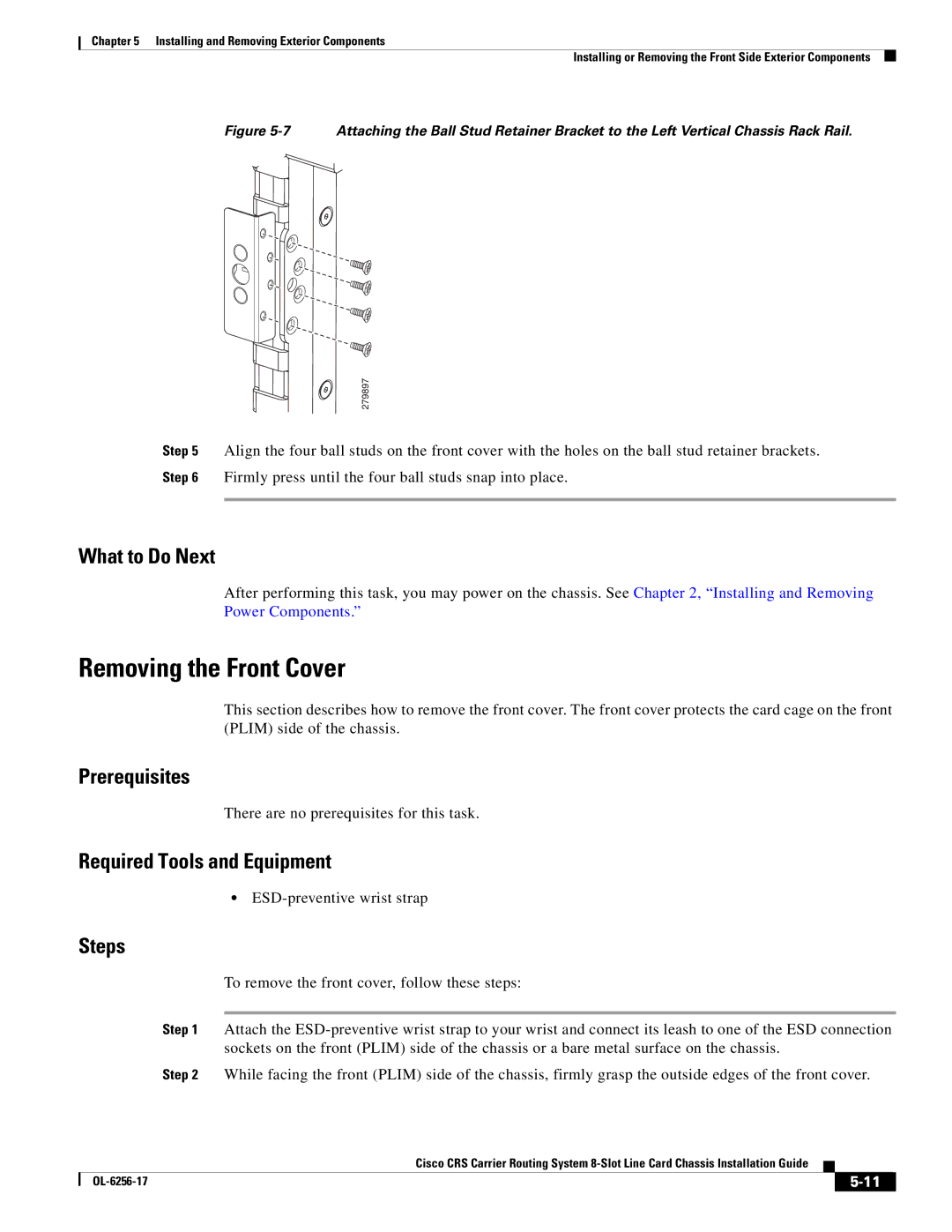
Figure 5-7 Attaching the Ball Stud Retainer Bracket to the Left Vertical Chassis Rack Rail.
279897
Step 5 Align the four ball studs on the front cover with the holes on the ball stud retainer brackets.
Step 6 Firmly press until the four ball studs snap into place.
What to Do Next
After performing this task, you may power on the chassis. See Chapter 2, “Installing and Removing Power Components.”
Removing the Front Cover
This section describes how to remove the front cover. The front cover protects the card cage on the front (PLIM) side of the chassis.
Prerequisites
There are no prerequisites for this task.
Required Tools and Equipment
•
Steps
To remove the front cover, follow these steps:
Step 1 Attach the
Step 2 While facing the front (PLIM) side of the chassis, firmly grasp the outside edges of the front cover.
Cisco CRS Carrier Routing System
|
| ||
|
|