Chapter 2 Installing and Removing Power Components
How to Install or Remove Modular Configuration Power Components
Required Tools and Equipment
You need the following tools to perform this task:
•
•
•5/32 x
•Two
•Modular configuration power shelf
–DC power shelf (Cisco product number
–AC power shelf (Cisco product number
Steps
To install the modular configuration power shelf, go to the rear of the chassis and perform the following steps:
Step 1 Attach the
Step 2 Ensure that all power cords are disconnected from the power shelf.
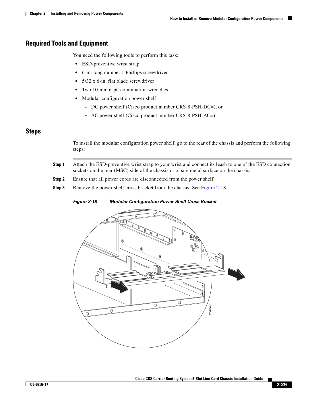
Step 3 Remove the power shelf cross bracket from the chassis. See Figure
Figure 2-18 Modular Configuration Power Shelf Cross Bracket
254849
Cisco CRS Carrier Routing System
|
| ||
|
|