|
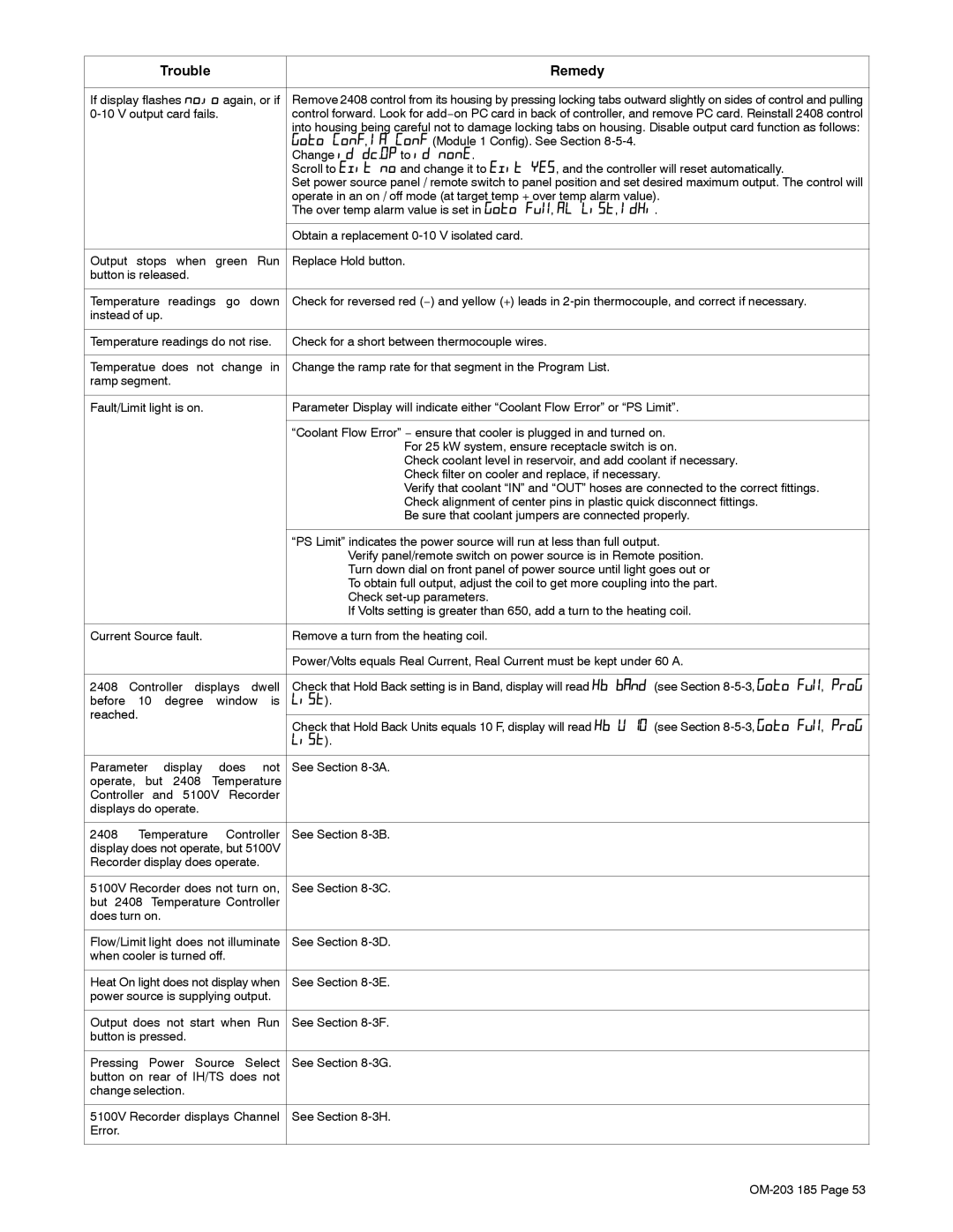
| Trouble |
|
| Remedy |
| ||
|
| |||||||
If display flashes no.io again, or if | Remove 2408 control from its housing by pressing locking tabs outward slightly on sides of control and pulling | |||||||
|
| control forward. Look for add−on PC card in back of controller, and remove PC card. Reinstall 2408 control | ||||||
|
|
|
|
|
|
| into housing being careful not to damage locking tabs on housing. Disable output card function as follows: | |
|
|
|
|
|
|
| Goto ConF, IA ConF (Module 1 Config). See Section |
|
|
|
|
|
|
|
| Change id dc.OP to id nonE. |
|
|
|
|
|
|
|
| Scroll to Exit no and change it to Exit YES, and the controller will reset automatically. |
|
|
|
|
|
|
|
| Set power source panel / remote switch to panel position and set desired maximum output. The control will | |
|
|
|
|
|
|
| operate in an on / off mode (at target temp + over temp alarm value). |
|
|
|
|
|
|
|
| The over temp alarm value is set in Goto Ful, AL LiSt, IdHi. |
|
|
|
|
|
|
|
|
|
|
|
|
|
|
|
|
| Obtain a replacement |
|
|
|
| ||||||
Output stops when green Run | Replace Hold button. |
| ||||||
button is released. |
|
|
|
|
| |||
|
|
|
|
|
| |||
Temperature | readings | go | down | Check for reversed red (−) and yellow (+) leads in |
| |||
instead of up. |
|
|
|
|
|
| ||
|
|
| ||||||
Temperature readings do not rise. | Check for a short between thermocouple wires. |
| ||||||
|
|
| ||||||
Temperatue does not change in | Change the ramp rate for that segment in the Program List. |
| ||||||
ramp segment. |
|
|
|
|
| |||
|
|
|
|
| ||||
Fault/Limit light is on. |
|
| Parameter Display will indicate either “Coolant Flow Error” or “PS Limit”. |
| ||||
|
|
|
|
|
|
|
|
|
|
|
|
|
|
|
| “Coolant Flow Error” − ensure that cooler is plugged in and turned on. |
|
|
|
|
|
|
|
| For 25 kW system, ensure receptacle switch is on. |
|
|
|
|
|
|
|
| Check coolant level in reservoir, and add coolant if necessary. |
|
|
|
|
|
|
|
| Check filter on cooler and replace, if necessary. |
|
|
|
|
|
|
|
| Verify that coolant “IN” and “OUT” hoses are connected to the correct fittings. |
|
|
|
|
|
|
|
| Check alignment of center pins in plastic quick disconnect fittings. |
|
|
|
|
|
|
|
| Be sure that coolant jumpers are connected properly. |
|
|
|
|
|
|
|
|
|
|
|
|
|
|
|
|
| “PS Limit” indicates the power source will run at less than full output. |
|
|
|
|
|
|
|
| Verify panel/remote switch on power source is in Remote position. |
|
|
|
|
|
|
|
| Turn down dial on front panel of power source until light goes out or |
|
|
|
|
|
|
|
| To obtain full output, adjust the coil to get more coupling into the part. |
|
|
|
|
|
|
|
| Check |
|
|
|
|
|
|
|
| If Volts setting is greater than 650, add a turn to the heating coil. |
|
|
|
|
|
| ||||
Current Source fault. |
|
| Remove a turn from the heating coil. |
| ||||
|
|
|
|
|
|
|
|
|
|
|
|
|
|
|
| Power/Volts equals Real Current, Real Current must be kept under 60 A. |
|
|
|
|
|
|
| |||
2408 | Controller | displays | dwell | Check that Hold Back setting is in Band, display will read Hb bAnd (see Section | ProG | |||
before 10 degree window is | LiSt). |
| ||||||
reached. |
|
|
|
|
|
|
| |
|
|
|
|
| Check that Hold Back Units equals 10 F, display will read Hb U 10 (see Section | ProG | ||
|
|
|
|
|
|
| ||
|
|
|
|
|
|
| LiSt). |
|
|
|
|
|
|
|
| ||
Parameter |
| display | does | not | See Section |
| ||
operate, but | 2408 Temperature |
|
| |||||
Controller | and 5100V | Recorder |
|
| ||||
displays do operate. |
|
|
|
| ||||
|
|
|
|
| ||||
2408 | Temperature | Controller | See Section |
| ||||
display does not operate, but 5100V |
|
| ||||||
Recorder display does operate. |
|
| ||||||
|
|
| ||||||
5100V Recorder does not turn on, | See Section |
| ||||||
but 2408 | Temperature Controller |
|
| |||||
does turn on. |
|
|
|
|
|
| ||
|
|
| ||||||
Flow/Limit light does not illuminate | See Section |
| ||||||
when cooler is turned off. |
|
|
| |||||
|
|
| ||||||
Heat On light does not display when | See Section |
| ||||||
power source is supplying output. |
|
| ||||||
|
|
| ||||||
Output does not start when Run | See Section |
| ||||||
button is pressed. |
|
|
|
|
| |||
|
|
|
|
| ||||
Pressing | Power | Source Select | See Section |
| ||||
button on rear of IH/TS does not |
|
| ||||||
change selection. |
|
|
|
|
| |||
|
|
| ||||||
5100V Recorder displays Channel | See Section |
| ||||||
Error. |
|
|
|
|
|
|
|
|
|
|
|
|
|
|
|
|
|
Page 57
Image 57