ES4710BD 10 Slots L2/L3/L4 Chassis Switch
13.3 Port Channel Example
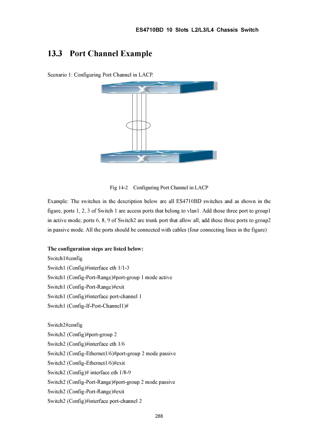
Scenario 1: Configuring Port Channel in LACP.
Fig
Example: The switches in the description below are all ES4710BD switches and as shown in the figure, ports 1, 2, 3 of Switch 1 are access ports that belong to vlan1. Add those three port to group1 in active mode; ports 6, 8, 9 of Switch2 are trunk port that allow all, add these three ports to group2 in passive mode. All the ports should be connected with cables (four connecting lines in the figure)
The configuration steps are listed below:
Switch1#config
Switch1 (Config)#interface eth
Switch1
Switch1
Switch1 (Config)#interface
Switch1
Switch2#config
Switch2
Switch2 (Config)#interface eth 1/6
Switch2
Switch2
Switch2 (Config)# interface eth
Switch2
Switch2
Switch2 (Config)#interface
288