ES4710BD 10 Slots L2/L3/L4 Chassis Switch
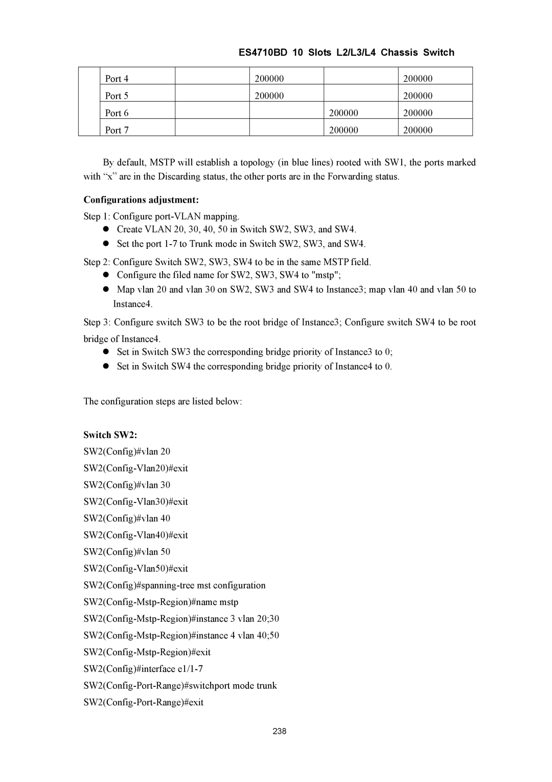
| Port 4 |
| 200000 |
| 200000 |
| Port 5 |
| 200000 |
| 200000 |
| Port 6 |
|
| 200000 | 200000 |
| Port 7 |
|
| 200000 | 200000 |
By default, MSTP will establish a topology (in blue lines) rooted with SW1, the ports marked with “x” are in the Discarding status, the other ports are in the Forwarding status.
Configurations adjustment:
Step 1: Configure
zCreate VLAN 20, 30, 40, 50 in Switch SW2, SW3, and SW4.
zSet the port
Step 2: Configure Switch SW2, SW3, SW4 to be in the same MSTP field.
zConfigure the filed name for SW2, SW3, SW4 to "mstp";
zMap vlan 20 and vlan 30 on SW2, SW3 and SW4 to Instance3; map vlan 40 and vlan 50 to Instance4.
Step 3: Configure switch SW3 to be the root bridge of Instance3; Configure switch SW4 to be root bridge of Instance4.
zSet in Switch SW3 the corresponding bridge priority of Instance3 to 0;
zSet in Switch SW4 the corresponding bridge priority of Instance4 to 0.
The configuration steps are listed below:
Switch SW2:
SW2(Config)#vlan 20
SW2(Config)#vlan 30
SW2(Config)#vlan 40
SW2(Config)#vlan 50
SW2(Config)#interface
238