|
|
| ES4710BD 10 Slots L2/L3/L4 Chassis Switch | ||
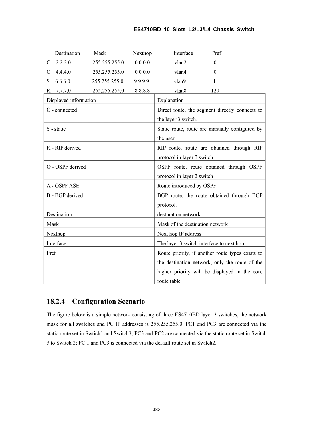
| Destination | Mask | Nexthop | Interface | Pref |
C | 2.2.2.0 | 255.255.255.0 | 0.0.0.0 | vlan2 | 0 |
C | 4.4.4.0 | 255.255.255.0 | 0.0.0.0 | vlan4 | 0 |
S | 6.6.6.0 | 255.255.255.0 | 9.9.9.9 | vlan9 | 1 |
R | 7.7.7.0 | 255.255.255.0 | 8.8.8.8 | vlan8 | 120 |
Displayed information |
| Explanation |
| ||
C - connected |
|
| Direct route, the segment directly connects to | ||
|
|
|
| the layer 3 switch. |
|
S - static |
|
| Static route, route are manually configured by | ||
|
|
|
| the user |
|
R - RIP derived |
|
| RIP route, route are obtained through RIP | ||
|
|
|
| protocol in layer 3 switch | |
O - OSPF derived |
|
| OSPF route, route obtained through OSPF | ||
|
|
|
| protocol in layer 3 switch | |
A - OSPF ASE |
|
| Route introduced by OSPF | ||
B - BGP derived |
|
| BGP route, the route obtained through BGP | ||
|
|
|
| protocol. |
|
Destination |
|
| destination network |
| |
Mask |
|
| Mask of the destination network | ||
Nexthop |
|
| Next hop IP address |
| |
Interface |
|
| The layer 3 switch interface to next hop. | ||
Pref |
|
| Route priority, if another route types exists to | ||
|
|
|
| the destination network, only the route of the | |
|
|
|
| higher priority will be displayed in the core | |
|
|
|
| route table. |
|
18.2.4Configuration Scenario
The figure below is a simple network consisting of three ES4710BD layer 3 switches, the network mask for all switches and PC IP addresses is 255.255.255.0. PC1 and PC3 are connected via the static route set in Swtich1 and Switch3; PC3 and PC2 are connected via the static route set in Switch 3 to Switch 2; PC 1 and PC3 is connected via the default route set in Switch2.
382
