|
|
| ES4710BD 10 Slots L2/L3/L4 Chassis Switch | |
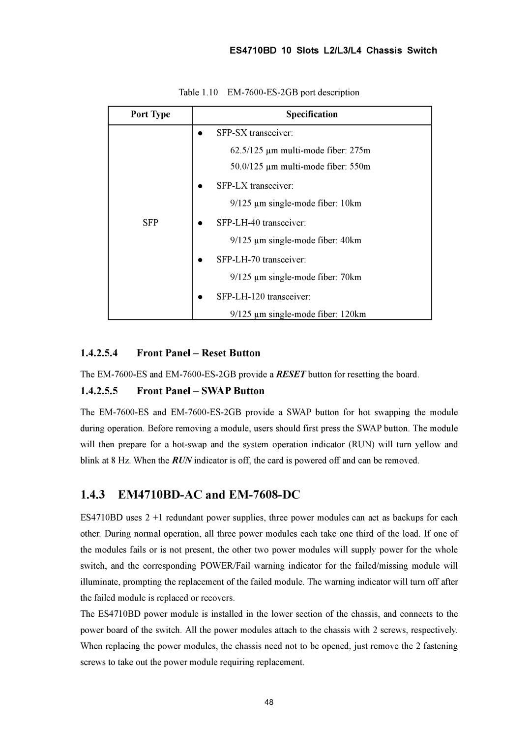
| Table 1.10 | |||
|
|
|
| |
Port Type |
|
| Specification |
|
|
|
|
| |
|
| z |
| |
|
|
| 62.5/125 µm |
|
|
|
| 50.0/125 µm |
|
|
| z |
| |
|
|
| 9/125 µm |
|
SFP |
| z |
| |
|
|
| 9/125 µm |
|
|
| z |
| |
|
|
| 9/125 µm |
|
|
| z |
| |
|
|
| 9/125 µm |
|
1.4.2.5.4Front Panel – Reset Button
The
1.4.2.5.5Front Panel – SWAP Button
The
1.4.3EM4710BD-AC and EM-7608-DC
ES4710BD uses 2 +1 redundant power supplies, three power modules can act as backups for each other. During normal operation, all three power modules each take one third of the load. If one of the modules fails or is not present, the other two power modules will supply power for the whole switch, and the corresponding POWER/Fail warning indicator for the failed/missing module will illuminate, prompting the replacement of the failed module. The warning indicator will turn off after the failed module is replaced or recovers.
The ES4710BD power module is installed in the lower section of the chassis, and connects to the power board of the switch. All the power modules attach to the chassis with 2 screws, respectively. When replacing the power modules, the chassis need not to be opened, just remove the 2 fastening screws to take out the power module requiring replacement.
48