ES4710BD 10 Slots L2/L3/L4 Chassis Switch
Connect with Ethernet cable
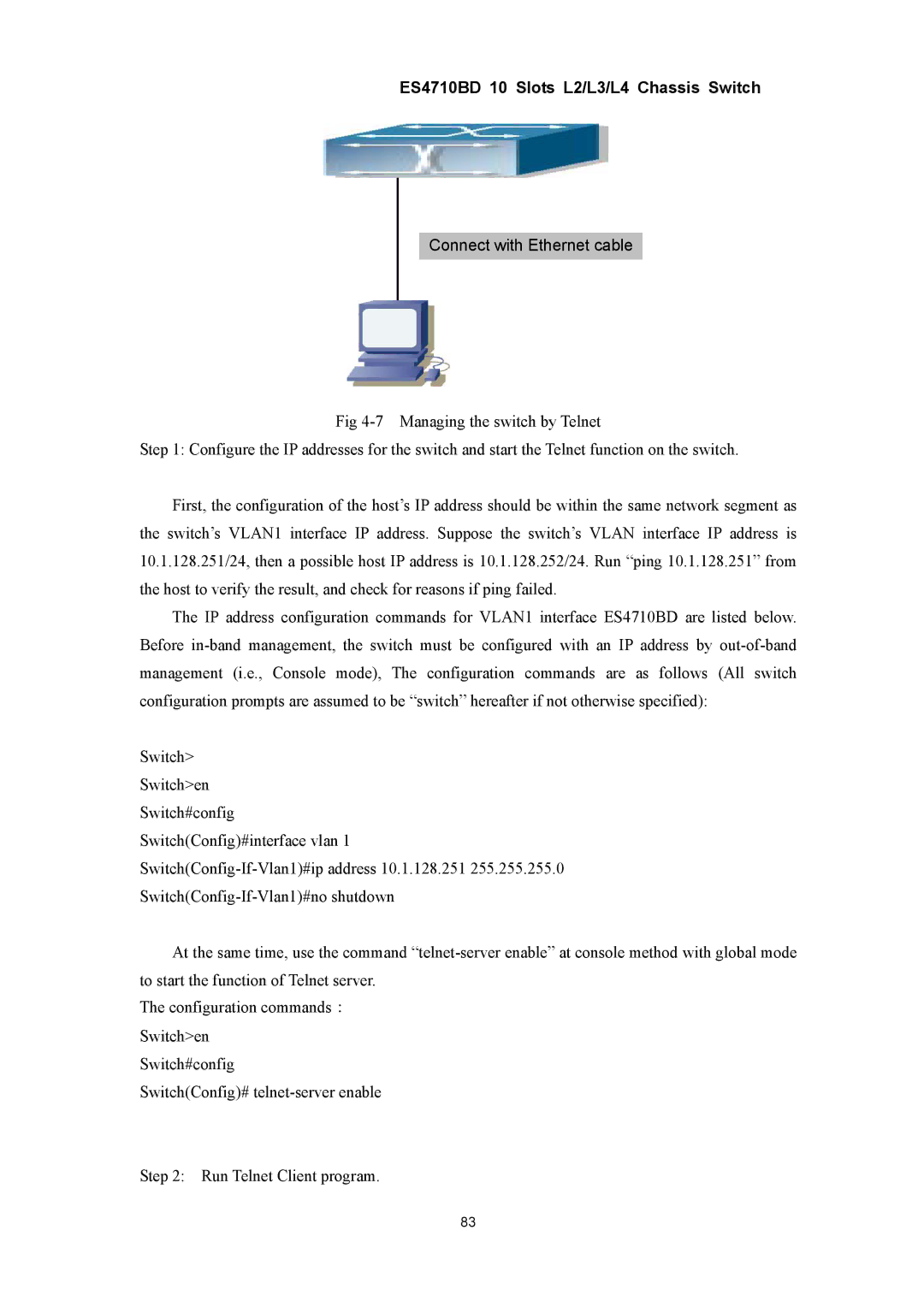
Fig
Step 1: Configure the IP addresses for the switch and start the Telnet function on the switch.
First, the configuration of the host’s IP address should be within the same network segment as the switch’s VLAN1 interface IP address. Suppose the switch’s VLAN interface IP address is 10.1.128.251/24, then a possible host IP address is 10.1.128.252/24. Run “ping 10.1.128.251” from the host to verify the result, and check for reasons if ping failed.
The IP address configuration commands for VLAN1 interface ES4710BD are listed below. Before
Switch>
Switch>en
Switch#config
Switch(Config)#interface vlan 1
At the same time, use the command
The configuration commands: Switch>en
Switch#config
Switch(Config)#
Step 2: Run Telnet Client program.
83